
Ring cutting device for cable processing

A loop cutting and cable technology, applied in cable installation devices, cable installation, equipment for dismantling/armored cables, etc., can solve the problems of low efficiency and labor consumption, achieve smooth incision, improve production efficiency, and meet the needs of use Effect

Active Publication Date: 2020-01-03
JING FENG GRP
View PDF6 Cites 6 Cited by
  • Summary
  • Abstract
  • Description
  • Claims
  • Application Information

AI Technical Summary

Problems solved by technology

[0003] The purpose of the present invention is to solve the problem of labor-intensive and low efficiency in the prior art, and propose a ring cutting device for cable processing

Method used


Image

  • Ring cutting device for cable processing
  • Ring cutting device for cable processing
  • Ring cutting device for cable processing

Examples


Embodiment 1

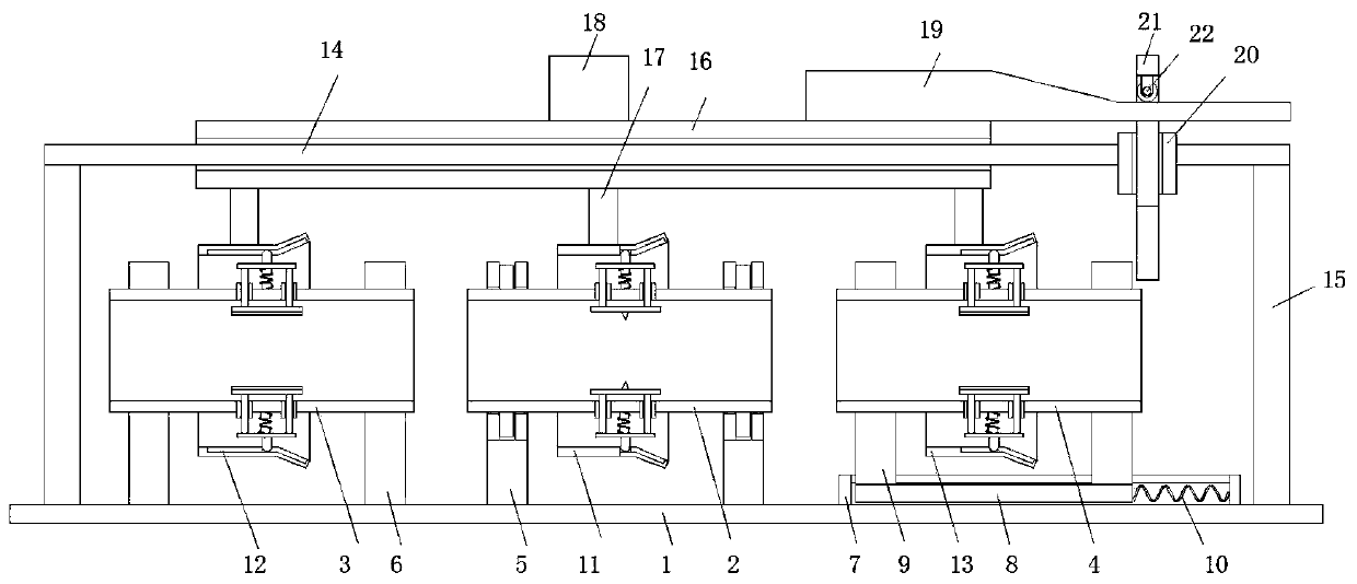
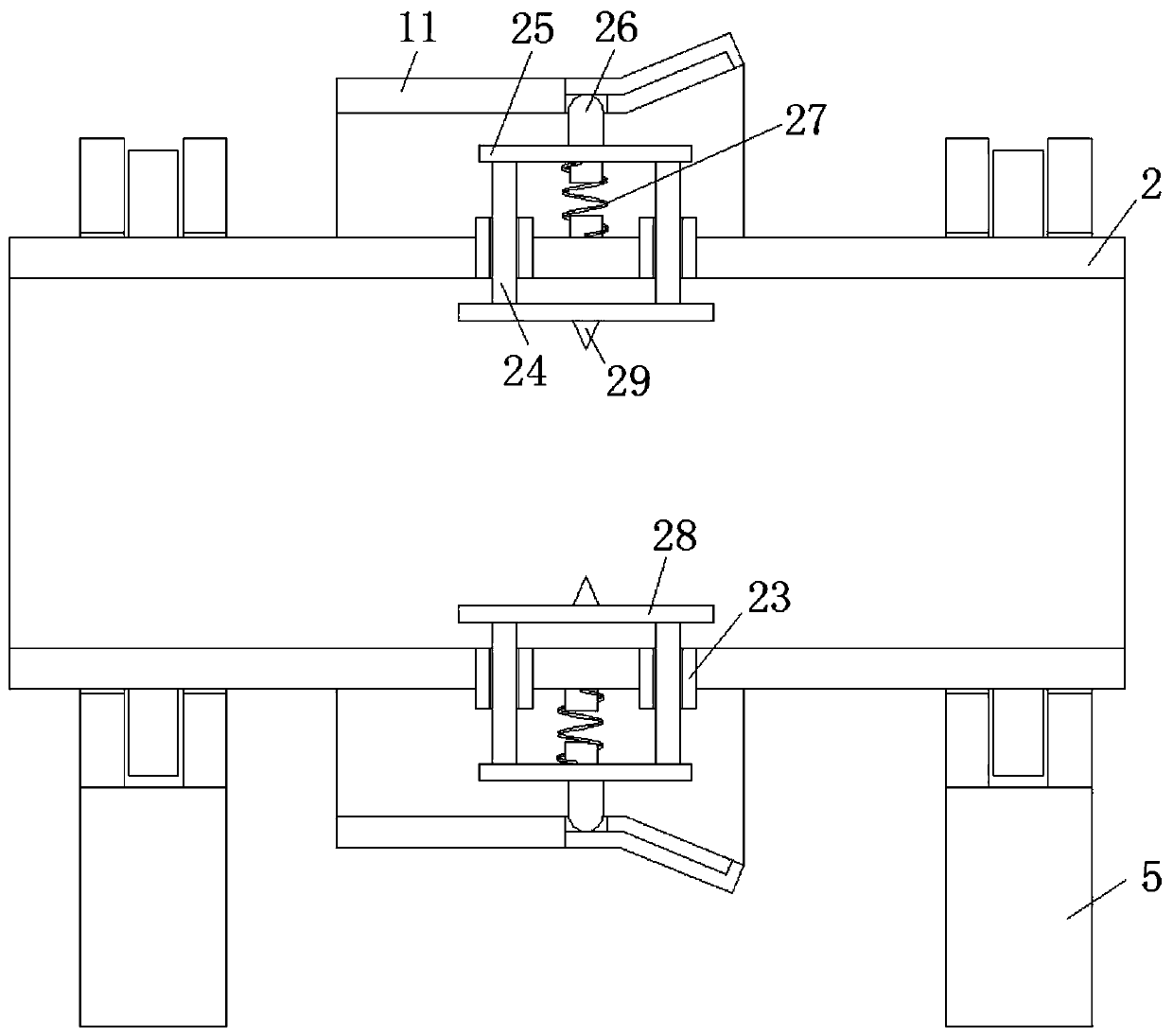
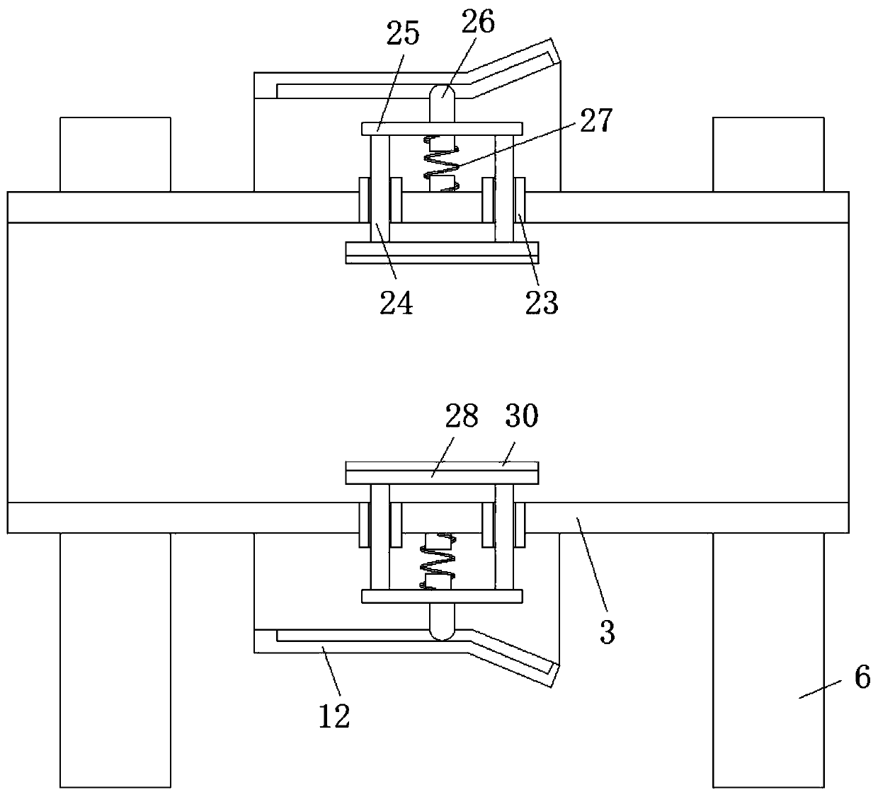
[0023] refer to Figure 1-4 , a ring cutting device for cable processing, comprising a bottom plate 1, a wire barrel 1 2, a wire barrel 2 3 and a wire barrel 3 4 are arranged vertically above the bottom plate 1, a wire barrel 2 3 and a wire barrel 3 4 are respectively arranged on both sides of the wire barrel 1 2, the bottom of the wire barrel 1 2 and the wire barrel 2 3 and the bottom plate 1 are respectively provided with a rotating seat 5 and a fixed base 6, and the top side of the bottom plate 1 is fixedly connected with a sliding seat 7. A chute is provided on the top side of the sliding seat 7, and a slide plate 8 is slidably connected in the chute, and a fixed seat 2 9 is arranged between the top side of the slide plate 8 and the wire barrel 3 4, and the slide plate 8 is far away from the wire barrel 1 2 A spring set 10 is arranged between one side of the chute and the inner wall of the chute, and the outer sides of the wire barrel 1 2, the wire barrel 2 3 and the wire ...

Embodiment 2

[0026] Such as Figure 1-4 As shown, this embodiment is basically the same as Embodiment 1. Preferably, the sliding cylinder one 20 is located vertically above the spring group one 10, and the bottom side of the sliding frame 21 and the fixing seat two 9 are far away from the one side of the wire cylinder one 2. side of the top contact connection.

[0027] In this embodiment, the friction force between the track groove 3 and the track rod 26 is prevented from driving the wire barrel 3 4 to move, which will affect the stability of the device.

Embodiment 3

[0029] Such as figure 1 As shown, this embodiment is basically the same as Embodiment 1. Preferably, the top side of the sliding sleeve 16 is fixedly welded with a push handle 18 .

[0030] In this embodiment, it is convenient for people to move the sliding sleeve 16 .


PUM


Abstract

The invention discloses a ring cutting device for cable processing. The device comprises a bottom plate, wherein a first wire passing barrel, a second wire passing barrel and a third wire passing barrel are vertically arranged above the bottom plate, the second wire passing barrel and the third wire passing barrel are arranged on two sides of the first wire passing barrel respectively, a rotatingbase and a fixed base are arranged between the bottoms of the first wire passing barrel and the second wire passing barrel and between bottom plates of the first wire passing barrel and the second wire passing barrel respectively, and a sliding base is fixedly connected with a top side of the bottom plate, a sliding groove is formed on the top side of the sliding base, a sliding plate is slidablyconnected into the sliding groove, a second fixing base is arranged between the top side of the sliding plate and the third wire passing barrel, a first spring set is arranged between the side, away from the first wire passing barrel, of the sliding plate and an inner wall of the sliding groove, and a first rail cylinder, a second rail cylinder and a third rail cylinder are arranged on outer sidesof the first wire passing cylinder, the second wire passing cylinder and the third wire passing cylinder in a sleeving mode correspondingly. The device is advantaged in that the cutting effect is guaranteed, manpower is saved, production efficiency is improved, and use requirements of people in production and life are met.

Description

technical field [0001] The invention relates to the technical field of cable processing, in particular to a ring cutting device for cable processing. Background technique [0002] In the process of processing and using the existing cables, it is necessary to cut the outer sheath of the cable at one end of the cable, so that the inner core of the cable is exposed and then docked. People manually cut the end of the cable, which is time-consuming. It is laborious, and the flatness of the incision is also poor, which cannot meet the needs of people in production and life. Contents of the invention [0003] The purpose of the present invention is to solve the problems of labor-consuming and low efficiency in the prior art, and propose a ring cutting device for cable processing. [0004] In order to achieve the above object, the present invention adopts the following technical solutions: [0005] A ring cutting device for cable processing, comprising a bottom plate, a wire bar...

Claims


Application Information

Patent Timeline
IPC IPC(8): H02G1/12
CPCH02G1/1265
Inventor 许义彬许德俊刘文林
Owner JING FENG GRP
Learn More