Valve mechanism, solenoid suction valve mechanism and high pressure fuel pump

A valve mechanism and valve core technology, used in fuel injection pumps, fuel injection devices, machines/engines, etc., can solve the problems of wear of the suction valve seat, failure of the suction valve to seal, and poor sealing performance, so as to improve flow control. sexual effect

Active Publication Date: 2021-10-08
HITACHI ASTEMO LTD
View PDF6 Cites 0 Cited by
  • Summary
  • Abstract
  • Description
  • Claims
  • Application Information

AI Technical Summary

Problems solved by technology

In this way, the sealing of the suction valve cannot be performed, and there is a problem that the flow rate is reduced or the flow controllability is deteriorated.
In addition, the suction valve contacting the suction valve seat portion obliquely causes wear of the suction valve seat portion, thereby deteriorating the sealing performance.

Method used


Image

  • Valve mechanism, solenoid suction valve mechanism and high pressure fuel pump
  • Valve mechanism, solenoid suction valve mechanism and high pressure fuel pump
  • Valve mechanism, solenoid suction valve mechanism and high pressure fuel pump

Examples


Embodiment

[0027] (overall composition)

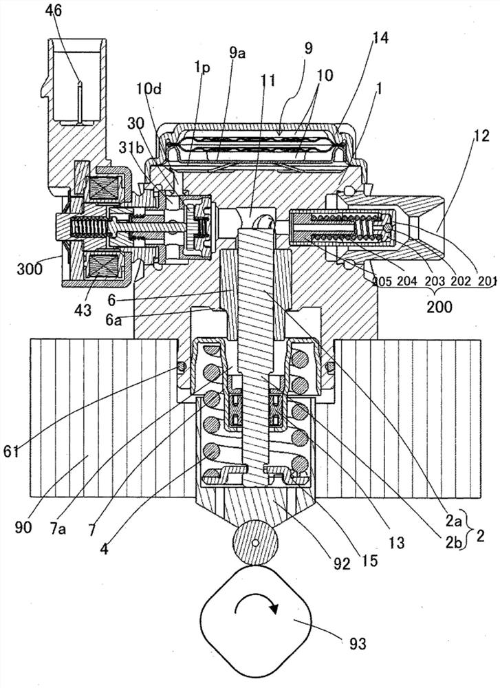
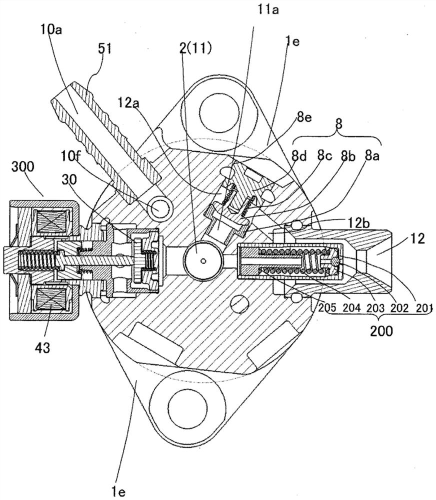
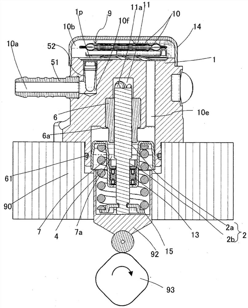
[0028] First, use Figure 5 The shown overall configuration diagram of the engine system explains the configuration and operation of the system. The part enclosed by the dotted line represents the main body of the high-pressure fuel pump, and the mechanisms and parts shown in the dotted line represent that they are integrally mounted on the pump body 1 .

[0029] The fuel of the fuel tank 20 is sucked by the feed pump 21 according to a signal from an engine control unit 27 (hereinafter referred to as ECU). The fuel is pressurized to the proper feed pressure and delivered through the suction line 28 to the low pressure fuel suction port 10a of the high pressure fuel pump. From the low-pressure fuel suction port 10a through the suction joint 51 (refer to figure 2 ) to the suction port 31b of the electromagnetic suction valve mechanism 300 constituting the capacity variable mechanism via the metal damper 9 (pressure pulsation reducing mechanism)...


PUM


Abstract

The present invention provides a valve mechanism, an electromagnetic suction valve mechanism, or a high-pressure fuel pump that suppresses radial movement of a suction valve and improves flow controllability even when high pressure and high flow are promoted. For this reason, the valve mechanism of the present invention is provided with: a spring member, which has a mounting ring portion and a movable portion, and is fixed by a spring support portion on the side opposite to the mounting ring portion; One side of the installation and positioning ring portion of the spring member exerts force; the valve core is formed with a convex portion that protrudes toward the side of the spring support portion and is located on the radially inner side of the spring member, which is constituted as In a sectional view cut along the axial direction of the spring member through the radial center of the spring member, two In terms of the cross-section of the coil on the side, the tip of the protrusion is located on one side of the spring support.

Description

technical field [0001] The invention relates to a valve mechanism, an electromagnetic suction valve mechanism and a high-pressure fuel pump. Background technique [0002] As the background art of the high-pressure fuel pump of the present invention, there are those described in Patent Documents 1 and 2. Patent Document 1 discloses the following content: "A high-pressure fuel pump is provided with a pump housing 1, a plunger 2, and an electromagnetic suction valve 300. The electromagnetic suction valve 300 has a valve 301c, and a valve seat for opening and closing the fuel passage by separating and contacting the valve 301c. 302a, and the valve stopper 313 for the valve 301c to abut against when the valve is opened, the electromagnetic suction valve 300 is installed in the electromagnetic suction valve insertion hole 1k formed on the pump casing 1, and the electromagnetic suction valve 300 is controlled to control the amount of discharged fuel. , wherein a bottom 1ka abuttin...

Claims


Application Information

Patent Timeline
Patent Type & Authority Patents(China)
IPC IPC(8): F02M59/36F02M59/34F02M59/44
CPCF02M55/04F02M59/368F02M63/0071F02M63/0077F02M2200/50
Inventor 齐藤淳治臼井悟史根本雅史秋山壮嗣德丸千彰内山康久早谷政彦小野濑亨枇本亘住谷登
Owner HITACHI ASTEMO LTD
Why Eureka
Try Eureka