Spring feeding control device in automatic tool

A control device and feeding technology, applied in the field of auto parts, can solve problems such as wrong and missing installation

Pending Publication Date: 2020-01-07
上海飞尔汽车零部件股份有限公司
View PDF0 Cites 0 Cited by
  • Summary
  • Abstract
  • Description
  • Claims
  • Application Information

AI Technical Summary

Problems solved by technology

[0004] The technical problem to be solved by the present invention is: how to avoid the problem of wrong or

Method used


Image

  • Spring feeding control device in automatic tool
  • Spring feeding control device in automatic tool
  • Spring feeding control device in automatic tool

Examples


Embodiment Construction

[0014] In order to make the present invention more comprehensible, preferred embodiments are described in detail below with accompanying drawings.

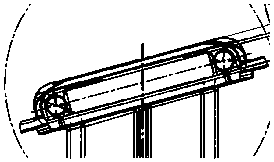
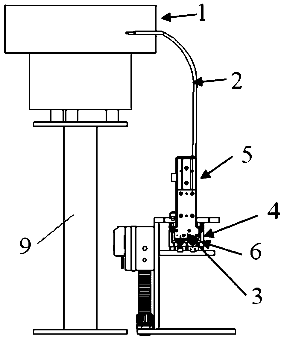
[0015] The invention is a spring feeding control device in an automatic tooling, such as image 3 , Figure 4 As shown, it includes a vibrating plate 1 for placing springs, the vibrating plate 1 is connected to one end of the spring feeding hose 2, the other end of the spring feeding hose 2 is connected to the upper end of the metal pipe 7, and the lower end of the metal pipe 7 The bottom is provided with a spring baffle 8 for blocking the spring, and the middle of the metal tube 7 is provided with a first hole for the passage of the spring limit pin 3. End connection, the lower end side of metal tube 7 is provided with the second hole that is used for spring clip 6 to clamp spring, and spring clip 6 is fixed on the telescopic end of sliding cylinder 5 up and down. Vibration plate 1 is fixed on the support frame 9 of its lower e...


PUM


Abstract

The invention discloses a spring feeding control device in an automatic tool. The device is characterized by comprising a vibration disc used for placing springs, the vibration disc communicates withone end of a spring feeding hose, the other end of the spring feeding hose communicates with the upper end of a metal pipe, a spring baffle used for blocking springs is arranged below the lower end ofthe metal pipe, the middle of the metal pipe is provided with a first hole allowing a spring limiting needle to pass through, the spring limiting needle and the spring baffle are connected with a telescopic end of a left and right sliding air cylinder, one side of the lower end of the metal pipe is provided with a second hole allowing a spring clamp to clamp the springs, and the spring clamp is fixed to the telescopic end of an up and down sliding air cylinder. The device is mainly used for operation of spring feeding in the car seat guide sleeve automatic tool, the air cylinder work principle is used for controlling the running track of the soft springs, it is ensured that the springs are precisely mounted in corresponding part holes, wrong arranging and missed arranging are avoided, thefailure frequency in tool running can be reduced, the waste damage rate is reduced, and the cost reducing and efficiency increasing of a factory are achieved.

Description

technical field [0001] The invention relates to a spring feeding control device in automatic tooling, which belongs to the technical field of auto parts. Background technique [0002] For the automatic tooling production of car seat guide bushes, if there are many parts and complex structures, the mechanism design will be complicated, the process will be many, the tooling cost will be high, the floor area will be large, and the processing will take a long time. [0003] Such as figure 1 As shown, it is an exploded diagram of the assembly of an existing guide bush. The difficulty in the assembly of this tool is how to control the two soft springs and install them into the two holes with a diameter of 3 mm in the guide bush body, and automatically identify whether there are any springs. Wrong installation, that is, two springs are installed in one hole, and the other guide sleeve hole is missing (no spring). In order to strengthen the description, the spring installation hol...

Claims


Application Information

Patent Timeline
IPC IPC(8): B23P19/04
CPCB23P19/001B23P19/004B23P19/048
Inventor 谢清王沈健邓扬盛
Owner 上海飞尔汽车零部件股份有限公司
Why Eureka
Try Eureka