Brake motor control method and device and vehicle

A brake motor and vehicle technology, which is applied in the field of vehicle engineering, can solve problems such as insufficient control precision of the brake motor, and achieve the effects of fine control, weight reduction of the vehicle body, and high energy utilization

Active Publication Date: 2020-01-07
BYD CO LTD
View PDF7 Cites 1 Cited by
  • Summary
  • Abstract
  • Description
  • Claims
  • Application Information

AI Technical Summary

Problems solved by technology

[0005] The present disclosure provides a control method and device for a brake motor, and a vehicle, so as to solve the problem of insufficient control precision of the brake motor in the related art

Method used


Image

  • Brake motor control method and device and vehicle
  • Brake motor control method and device and vehicle
  • Brake motor control method and device and vehicle

Examples


Embodiment Construction

[0049] Specific embodiments of the present disclosure will be described in detail below in conjunction with the accompanying drawings. It should be understood that the specific embodiments described here are only used to illustrate and explain the present disclosure, and are not intended to limit the present disclosure.

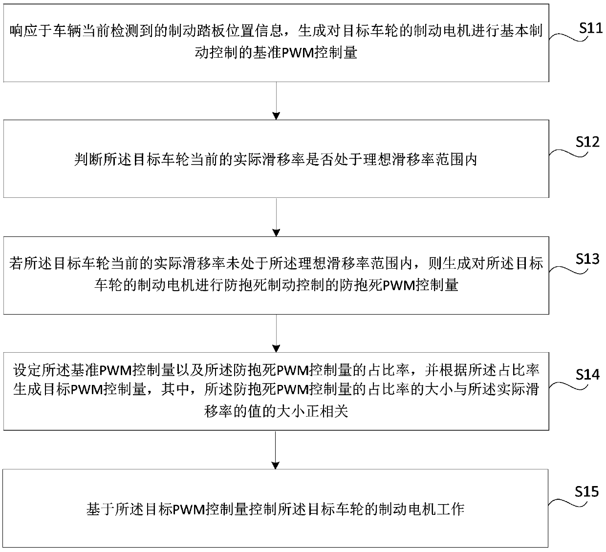
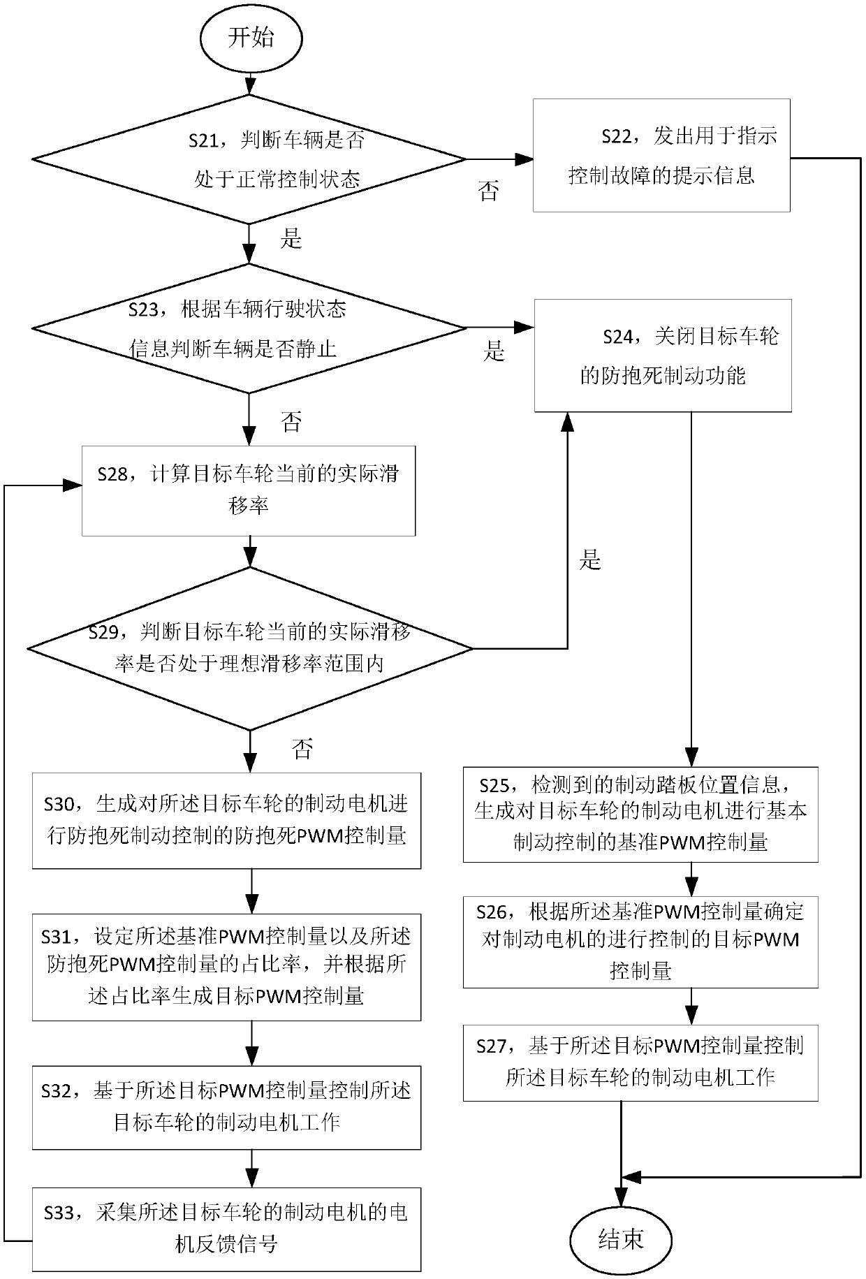
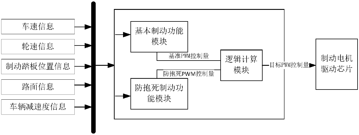
[0050] figure 1It is a flowchart of a method for controlling a braking motor according to an exemplary embodiment. The method can be applied to an active control braking system, that is, an active control braking system that drives a mechanical structure through a brushless motor to push a caliper to clamp a brake disc to achieve braking.

[0051] Such as figure 1 As shown, the method includes:

[0052] S11, in response to the brake pedal position information currently detected by the vehicle, generate a reference PWM control amount for performing basic brake control on the brake motor of the target wheel.

[0053] Specifically, according to the position ...


PUM


Abstract

The invention provides a brake motor control method and device and a vehicle in order to solve the problem that the control precision of a brake motor is insufficient in the prior art. The method comprises the steps of making a response to currently-detected brake pedal position information of the vehicle to generate the datum PWM control quantity of basic brake control over a brake motor of a target wheel; judging whether the current actual slip rate of the target wheel is within an ideal slip rate range or not; generating the anti-lock PWM control quantity of anti-lock brake control over thebrake motor of the target wheel if the current actual slip rate of the target wheel is not within the ideal slip rate range; setting the ratio of the datum PWM control quantity to the anti-lock PWM control quantity and generating the target PWM control quantity according to the ratio; and controlling the brake motor of the target wheel to operate based on the target PWM control quantity.

Description

technical field [0001] The present disclosure relates to the field of vehicle engineering, in particular, to a control method and device for a brake motor, and a vehicle. Background technique [0002] Locking means that the tires no longer rotate during the braking process of the car. It is easy to cause the car to lose control, causing traffic accidents and other hazards. [0003] In the related art, a brake control system (ABS, Antilock Brake System) is proposed that implements anti-lock braking through a solenoid valve / hydraulic regulator unit of a hydraulic regulator. When the hydraulic anti-lock braking system ABS is running, if the driving state of the vehicle is in a normal state, the oil inlet solenoid valve of the hydraulic regulator is in the position of "building pressure" during the braking process, that is, the inlet valve is straight through , the braking pressure established by the brake master cylinder can be directly transmitted to the wheel cylinders of e...

Claims


Application Information

Patent Timeline
Patent Type & Authority Applications(China)
IPC IPC(8): B60T8/17B60T8/172H02P29/00
CPCB60T8/17B60T8/172H02P29/00
Inventor 杨欣澍
Owner BYD CO LTD
Why Eureka
Try Eureka