Pre-grouting type semi-grouting sleeve structure and construction method

A semi-grouting sleeve and grouting material technology, which is applied to structural elements, building components, building structures, etc., can solve problems such as complex grouting operations and difficult quality assurance, so as to simplify the construction process, improve construction efficiency, and avoid The effect of the grouting operation

Pending Publication Date: 2020-01-07
NO 2 CONSTR GRP CO LTD OF SHANGHAI CONSTR GRP
View PDF5 Cites 2 Cited by
  • Summary
  • Abstract
  • Description
  • Claims
  • Application Information

AI Technical Summary

Problems solved by technology

[0003] The grouting sleeve has a wide range of applications, but requires complex grouting operations, and its quality is difficult to guarantee

Method used


Image

  • Pre-grouting type semi-grouting sleeve structure and construction method
  • Pre-grouting type semi-grouting sleeve structure and construction method

Examples


Embodiment 1

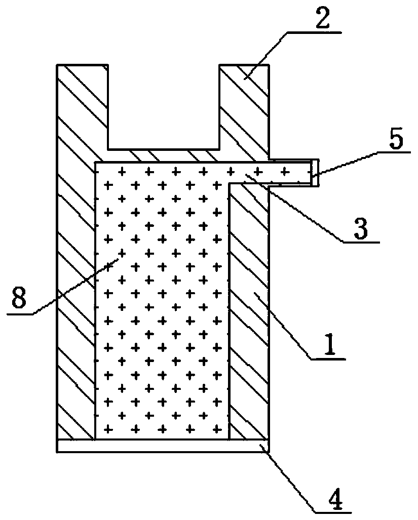
[0023] refer to Figure 1 to Figure 2 , this embodiment provides a pre-grouting semi-grouting sleeve structure, including a grout cylinder 1, and a steel bar connector 2 arranged outside the bottom of the grout cylinder 1, the wall of the grout cylinder 1 is provided with The slurry overflow hole 3, the mouth of the slurry cylinder 1 is provided with a cylinder mouth cover 4, the overflow opening of the slurry overflow hole 3 is provided with a slurry overflow cover 5, and the slurry cylinder 1 is filled with a grouting material 8.

[0024] A kind of pre-grouting semi-grouting sleeve structure of this embodiment, the grouting material 8 is prefabricated in the grouting material cylinder 1, when constructing the pre-grouting type semi-grouting sleeve structure, only need to directly insert the steel bar 7 to be connected The slurry tank 1 gets final product. Compared with the traditional grouting sleeve construction process, the grouting operation is eliminated, the constructi...

Embodiment 2

[0029] This embodiment provides a construction method for the pre-grouted semi-grouting sleeve structure described in Embodiment 1.

[0030] The technical characteristics of the construction method of the pre-grouting type semi-grouting sleeve structure of the present embodiment are as follows, comprising the steps:

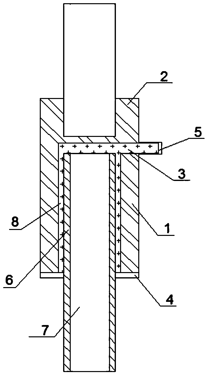
[0031] In the first step, the grouting material 8 is filled in the grouting material cylinder 1 of the pre-grouting type semi-grouting sleeve structure;

[0032] In the second step, during the prefabricated component manufacturing process, the pre-grouted half-grouted sleeve structure is embedded in the prefabricated component, and the steel bar connector 2 of the pre-grouted half-grouted sleeve structure is connected to the internal steel bars of the prefabricated component;

[0033] The third step is to remove the overflow cover 5;

[0034] The fourth step is to insert the steel bar 7 to be connected into the slurry cylinder 1 from the mouth of the slurry cyli...


PUM


Abstract

The invention provides a pre-grouting type semi-grouting sleeve structure and a construction method in order to simplify the construction technology of a grouting sleeve and improve the construction efficiency of the grouting sleeve. The pre-grouting type semi-grouting sleeve structure comprises a slurry cylinder, and a steel bar connector arranged on the outer side of the cylinder bottom of the slurry cylinder. A slurry overflowing hole is formed in the cylinder wall of the slurry cylinder. A cylinder opening sealing sleeve is arranged at a cylinder opening of the slurry cylinder. A slurry overflowing opening sealing sleeve is arranged at a slurry overflowing opening of the slurry overflowing hole. The slurry cylinder is filled with slurry. According to the pre-grouting type semi-groutingsleeve structure, the slurry is prefabricated into the slurry cylinder, and when the pre-grouting type semi-grouting sleeve structure carries out construction, a steel bar to be connected only needsto be inserted into the slurry cylinder. In comparison with the construction technology of a traditional grouting sleeve, grouting operation is omitted, the construction technology of the grouting sleeve is simplified, and the construction efficiency of the grouting sleeve is improved.

Description

technical field [0001] The invention belongs to the technical field of prefabricated assembly engineering, and in particular relates to a pre-grouting type semi-grouting sleeve and a construction method. Background technique [0002] Grouting sleeve is one of the commonly used steel bar connection methods in prefabricated buildings in my country. In the grouting sleeve, the joint that is threaded at one end and grouted at the other end is called a half-grouting sleeve. In the grouting sleeve, the grouting material is generally a dry mix made of cement as the basic material and mixed with fine aggregate, admixtures and other materials. The hardened grouting material is respectively gripped with the steel bar and the grouting sleeve to realize the connection structure of continuous and reliable force transmission of the steel bar. [0003] The grouting sleeve has a wide range of applications, but requires complex grouting operations, and its quality is difficult to guarantee...

Claims


Application Information

Patent Timeline
Patent Type & Authority Applications(China)
IPC IPC(8): E04C5/16
CPCE04C5/165
Inventor 龙莉波马跃强戚健文
Owner NO 2 CONSTR GRP CO LTD OF SHANGHAI CONSTR GRP
Why Eureka
Try Eureka