
Active target positioning method and system of airborne photoelectric pod

A target positioning, photoelectric pod technology, applied in the field of target positioning, can solve the problems of low positioning accuracy, difficult measurement and elimination, unstable randomness of target positioning result errors, etc.

Active Publication Date: 2020-01-07
中国人民解放军火箭军工程大学
View PDF8 Cites 6 Cited by
  • Summary
  • Abstract
  • Description
  • Claims
  • Application Information

AI Technical Summary

Problems solved by technology

[0004] The calculation process of the target single point positioning algorithm involves the conversion of multiple coordinate systems. Combining the attitude angle of the UAV and the attitude angle of the optoelectronic platform, the coordinates of the target position are calculated. However, this method introduces the Angle, angle measuring instruments have measurement errors, and angle errors contribute greatly to positioning errors. Both the attitude angle error of the drone and the attitude angle error of the photoelectric platform will be directly transmitted to the positioning error of the target, and it is not easy to measure and eliminate. In the end, the positioning accuracy is not high, and the error of the calculated target positioning result is unstable and random
[0005] The recursive least squares multi-point ranging positioning algorithm uses multiple waypoints on the UAV route to measure the distance of the target, and the obtained ranging information is used as the measurement information to calculate the positioning result of the target. This method is called The least squares multipoint positioning algorithm, the least squares multipoint ranging positioning algorithm can further reduce the impact of bad measurement points on the positioning results, when the target is estimated based on the recursive least squares multipoint ranging And when the target is static, the positioning accuracy is high, and the error can be controlled within 10m, but this method has the problem of being unable to locate the dynamic target and measure the speed

Method used


Image

  • Active target positioning method and system of airborne photoelectric pod
  • Active target positioning method and system of airborne photoelectric pod
  • Active target positioning method and system of airborne photoelectric pod

Examples


Embodiment Construction

[0066] The following will clearly and completely describe the technical solutions in the embodiments of the present invention with reference to the accompanying drawings in the embodiments of the present invention. Obviously, the described embodiments are only some, not all, embodiments of the present invention. Based on the embodiments of the present invention, all other embodiments obtained by persons of ordinary skill in the art without making creative efforts belong to the protection scope of the present invention.

[0067] The object of the present invention is to provide an active target positioning method and system for an airborne photoelectric pod to realize real-time positioning of the target.

[0068] In order to make the above objects, features and advantages of the present invention more comprehensible, the present invention will be further described in detail below in conjunction with the accompanying drawings and specific embodiments.

[0069] The calculation pr...


PUM


Abstract

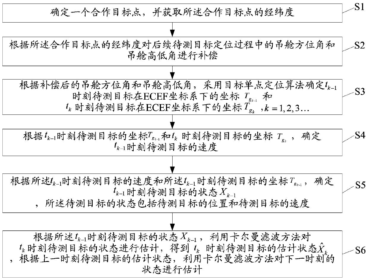
The invention discloses an active target positioning method and system of an airborne photoelectric pod. The method comprises the steps: determining a cooperative target point and acquiring the longitude and latitude of the cooperative target point; compensating a pod azimuth angle and a pod elevation angle in the subsequent positioning process of a to-be-measured target according to the longitudeand latitude of the cooperative target point; according to the compensated data, determining coordinates of the to-be-measured target at a tk-1 moment and a tk moment under an ECEF coordinate systembased on a target single-point positioning algorithm and determining the speed of the to-be-measured target at a tk-1 moment based on the coordiantes; and determining a state Xk-1 of the to-be-measured target at the tk-1 moment according to the speed of the to-be-measured target at the tk-1 moment and the coordinate of the to-be-measured target at the tk-1 moment, estimating the state of the to-be-measured target at the tk moment by using Kalman filtering method according to the state Xk-1 of the to-be-measured target to obtain an estimated state of the to-be-measured target at the tk moment,and estimating the state at a next time by using the Kalman filtering method according to the estimated state of the to-be-measured target at the previous moment. Therefore, real-time high-precision positioning of the target is realized.

Description

technical field [0001] The invention relates to the technical field of target positioning, in particular to an active target positioning method and system for an airborne photoelectric pod. Background technique [0002] The main task of target positioning is to obtain the three-dimensional coordinates of the target in the earth coordinate system. During the target positioning process, the video image and telemetry information are transmitted to the ground station for display through the data link system. The manipulator controls the stable platform and the camera system to search for the reconnaissance target through the joystick and other instructions. When the target of interest appears on the screen, It can lock and track the target, make the target in the center of the screen, freeze the image and save the aerial attitude measurement data of the aircraft platform, the GNSS navigation information received by the aircraft, the visual axis position of the airborne photoelec...

Claims


Application Information

Patent Timeline
IPC IPC(8): G01C21/20G01C21/00
CPCG01C21/005G01C21/20
Inventor 金国栋谭力宁李建波蔡幸福芦利斌陈丹琪
Owner 中国人民解放军火箭军工程大学
Learn More