
Metal sheet high-speed tensile test device driven by electromagnetic force

A technology of high-speed stretching and metal sheeting, which is applied in measuring devices, using stable tension/pressure testing materials, instruments, etc., can solve problems such as difficulty in implementation and expensive equipment, and achieve low experimental cost, accurate establishment, and stress. - Strain curve accurate effect

Active Publication Date: 2020-01-07
华瞬(深圳)智能装备有限公司
View PDF6 Cites 8 Cited by
  • Summary
  • Abstract
  • Description
  • Claims
  • Application Information

AI Technical Summary

Problems solved by technology

[0004] Aiming at the problems of expensive high-speed tensile test equipment and difficult implementation in the prior art, the present invention proposes a high-speed tensile test device for thin metal plates driven by electromagnetic force, which uses a simple structure to complete the tensile test of the plate under high-speed conditions. It can easily measure the stress of a certain area of ​​the metal sheet during high-speed stretching, and complete the formability test of the sheet under high-speed conditions.

Method used


Image

  • Metal sheet high-speed tensile test device driven by electromagnetic force
  • Metal sheet high-speed tensile test device driven by electromagnetic force
  • Metal sheet high-speed tensile test device driven by electromagnetic force

Examples


Embodiment Construction

[0047] In order to enable those skilled in the art to better understand the technical solutions of the present application, the present invention will be further described in detail below in conjunction with specific embodiments and accompanying drawings.

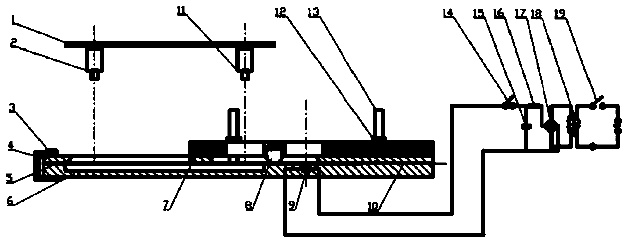
[0048] This embodiment describes a metal sheet high-speed tensile test device driven by electromagnetic force, such as figure 1 As shown, the tensile test device includes: a lifting bracket 1, a stress shooting camera 2, a C-shaped clamp 3, an insulating rigid plate 4, a tensile sample 5, an experimental platform 6, a steel plate pressing block 7, an insulating insert 8, Insulation gasket 10, strain shooting camera 11, fastening nut 12, support stud 13 and power supply unit.

[0049] The stress photographing camera 2 and the strain photographing camera 11 are respectively fixed at preset positions on the elevating support 1, and the elevating support 1 can carry the stress photographing camera 2 and the strain photographing...


PUM


Abstract

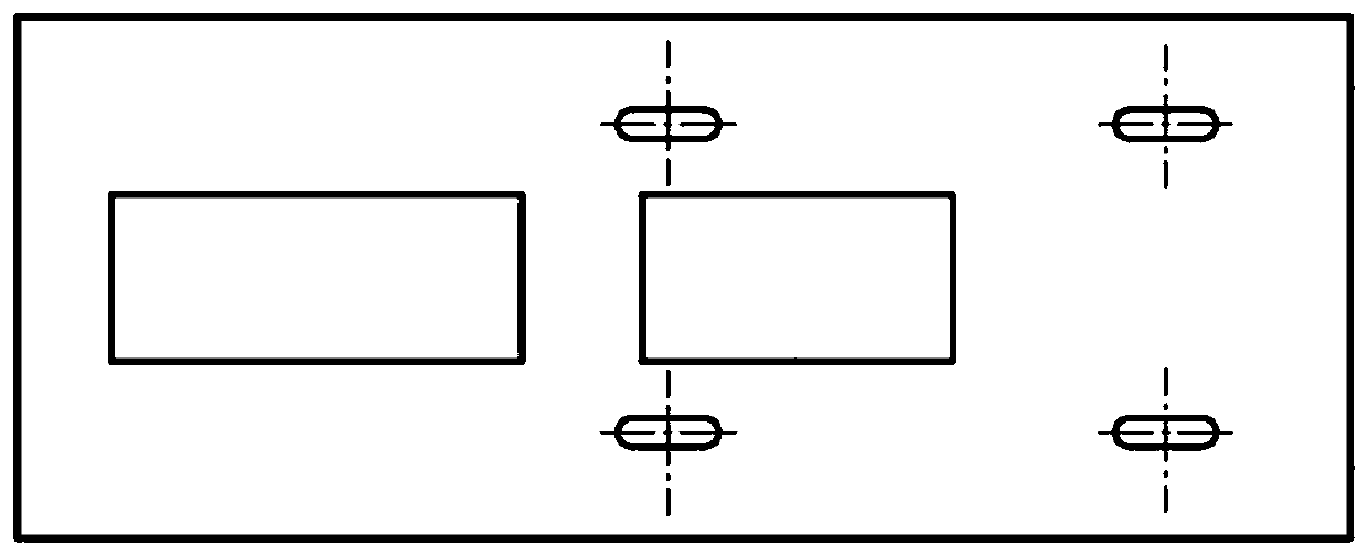
The invention relates to a metal sheet high-speed tensile test device driven by electromagnetic force. The tensile test device comprises a stress shooting camera, an insulating rigid plate, an experimental platform, a strain shooting camera and a power supply unit; a tensile sample is pressed on the experimental platform through the insulating rigid plate; two square holes in the middle of the insulating rigid plate are positioned above two speckle areas of the tensile sample respectively; a groove is formed in the left half part of the upper surface of the experimental platform and located under two speckle areas of the tensile sample, and a coil base in the right half part of the experimental platform is located under the right sides of the two speckle areas of the tensile sample; the power supply unit comprises a coil, and the coil is electrified to generate an electromagnetic force acted on the tensile sample, so that the right side of the tensile sample expands at high speed to drive the left side to generate tensile deformation; and the stress shooting camera and the strain shooting camera face the two speckle areas of the tensile sample respectively to acquire deformation information of the tensile sample. According to the test device, a stress-strain curve of the material in the high-speed deformation process can be quickly and accurately obtained.

Description

technical field [0001] The invention relates to a plate stretching device, in particular to a high-speed stretching test device for a thin metal plate driven by electromagnetic force. Background technique [0002] Plastic processing has the remarkable characteristics of high yield, high quality and low consumption, and has become an important development direction of today's advanced manufacturing technology. According to expert research, in the new era of the 21st century, 75% of the rough machining and 50% of the finishing of product parts will be realized by plastic forming. The extensive demand of the industrial sector provides a strong driving force for the development of new plastic processing technology and new equipment. The plastic forming process of the sheet metal will be affected by many factors. For example, the plastic deformation law of the material is very different under different strain rates. become increasingly important. The most practical method for ...

Claims


Application Information

Patent Timeline
IPC IPC(8): G01N3/08
CPCG01N3/08G01N2203/0003G01N2203/0017G01N2203/005G01N2203/0075G01N2203/0282G01N2203/0647G01N2203/0676G01N2203/0682
Inventor 柳泉潇潇
Owner 华瞬(深圳)智能装备有限公司
Learn More