Camera module and electronic equipment

A technology for camera modules and electronic equipment, which is applied in the direction of television, electrical components, image communication, etc., can solve the problems of high cost and complex structure of electronic equipment, and achieve the effect of low manufacturing cost and simple structure

Active Publication Date: 2020-01-07
VIVO MOBILE COMM CO LTD
12 Cites 21 Cited by

AI-Extracted Technical Summary

Problems solved by technology

[0004] The invention discloses a camera module and electronic equipment to solve the problem that the current electronic equipment is specially equipped with a driv...

Method used

In a more preferred solution, the axis of the first hinge shaft 330 can be perpendicular to the axis of the second hinge shaft. In this case, the tilt angle generated by the shaking of the entire camera module during shooting is easier It is decomposed into two angle components respectively around the direction of the first hinge axis 330 and the direction around the second hinge axis, so as to facilitate the angle compensation of the camera 310 during the rotation process.
In a more preferred solution, the first bracket 320 can also include a second connecting arm 324, the first end of the second connecting arm 324 is fixedly connected with the bracket main body 321, and the second end of the second connecting arm 324 is free end. The first hinge shaft 330 is fixed on the second bracket 340 or the camera head 310, and the second end of the second connecting arm 324 is provided with a first hinge hole 325, and the first hinge hole 325 is hinged with the first hinge shaft 330, similarly, the second The second ends of the two connecting arms 324 can extend into the inner cavity 110 of the casing to realize hinge, which is beneficial to the miniaturization design of the whole module bracket. At the same time, the second connecting arm 324 is a cantilever structure, and the first hinge hole 325 is disposed at the free end of the second connecting arm 324 , so it is easier to realize hinged assembly through deformation of the second connecting arm 324 .
In the embodiment of the present invention, there can be multiple mechanisms for driving the module housing 100 to rotate, please refer to FIG. and the arc rack 231 , the arc rack 231 is fixedly connected with the module housing 100 , the drive gear 220 meshes with the arc rack 231 , and the power output shaft of the drive motor 210 is connected to the drive gear 220 through transmission. The use of gear mechanism for power transmission has the advantages of relatively stable transmission and high transmission precision. The arc rack 231 can ensure the rotation of the module casing 100 within a certain angle, and this structure is more suitable for driving the rotation of the module casing 100 within a certain angle range. Of course, the arc rack 231 can be replaced by an annular rack.
Please refer to Fig. 3 again, in a more preferred solution, the driving mechanism 200 can include an annular structural member 230, and the annular structural member 230 can be arranged around the module housing 100, and the annular structural member 230 and the module housing The body 100 is fixedly connected, and the ring structure 230 includes an arc rack 231 . The annular structural member 230 ...

Abstract

The invention discloses a camera module. The module comprises a module shell (100), a driving mechanism (200) and a mechanical anti-shake camera assembly (300), wherein the module shell (100) is provided with a shell inner cavity (110); a mechanical anti-shake camera assembly (300) is at least partially arranged in the inner cavity (110) of the shell. The mechanical anti-shake camera assembly (300) can rotate along with the module shell (100). The driving mechanism (200) is connected with the module shell (100); the mechanical anti-shake camera assembly (300) comprises a camera (310). When thecamera (310) is located at the first position, the camera (310) is rotated; the lens axis of the camera (310) coincides with or is parallel to the rotating axis of the module shell (100), when the camera (310) is located at the second position, an included angle is formed between the lens axis and the rotating axis of the module shell (100), and the driving mechanism (200) drives the module shell(100) to rotate. The invention discloses an electronic device. According to the scheme, the structure of the camera module can be simplified, and the manufacturing cost of the camera module is reduced.

Application Domain

Technology Topic

Image

  • Camera module and electronic equipment
  • Camera module and electronic equipment
  • Camera module and electronic equipment

Examples

  • Experimental program(1)

Example Embodiment

[0026] In order to make the objectives, technical solutions and advantages of the present invention clearer, the technical solutions of the present invention will be described clearly and completely with reference to specific embodiments of the present invention and the corresponding drawings. Obviously, the described embodiments are only a part of the embodiments of the present invention, rather than all the embodiments. Based on the embodiments of the present invention, all other embodiments obtained by those of ordinary skill in the art without creative work shall fall within the protection scope of the present invention.
[0027] The technical solutions disclosed in the various embodiments of the present invention will be described in detail below with reference to the accompanying drawings.
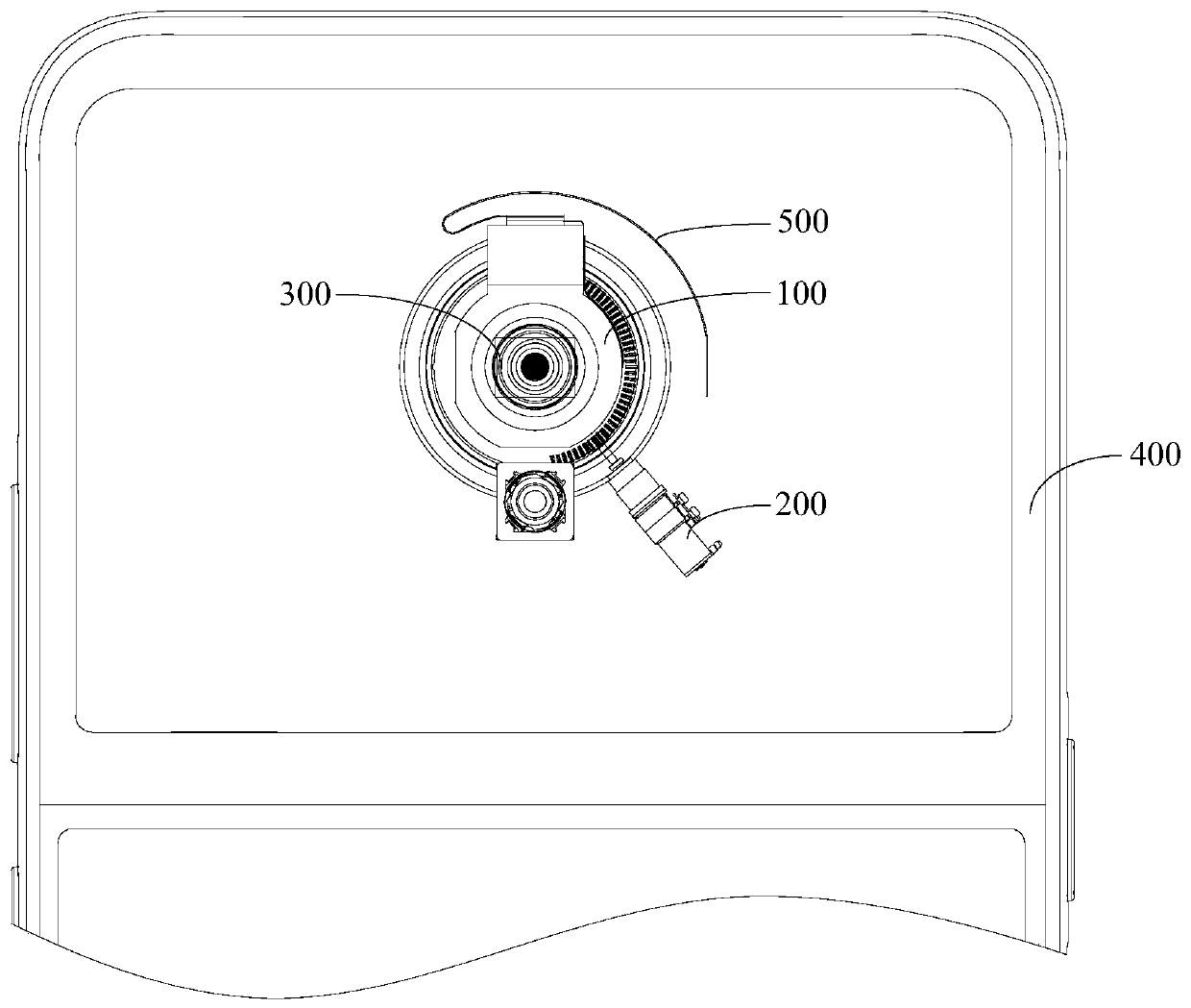
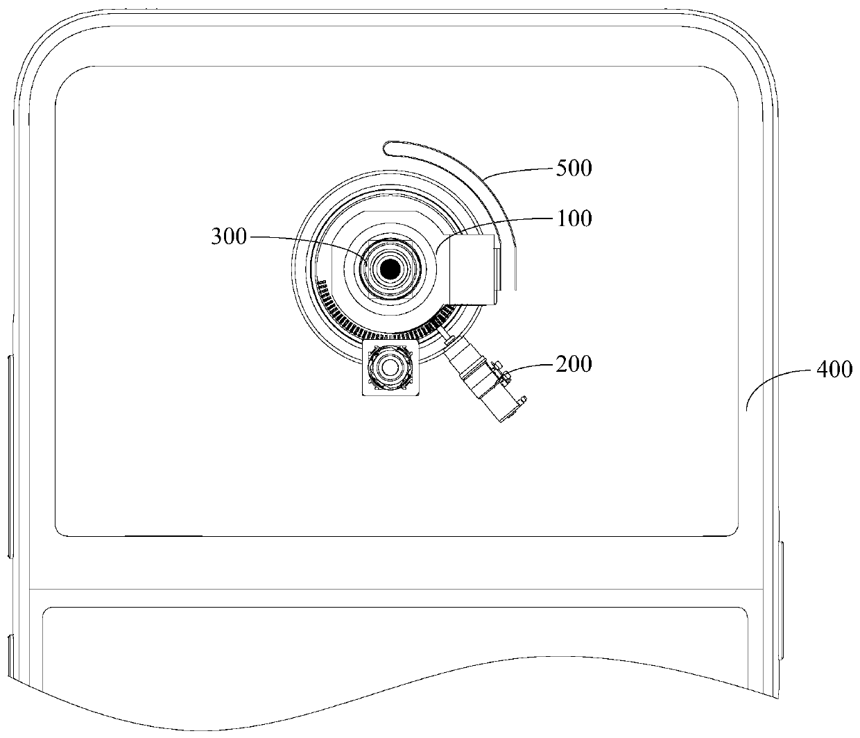
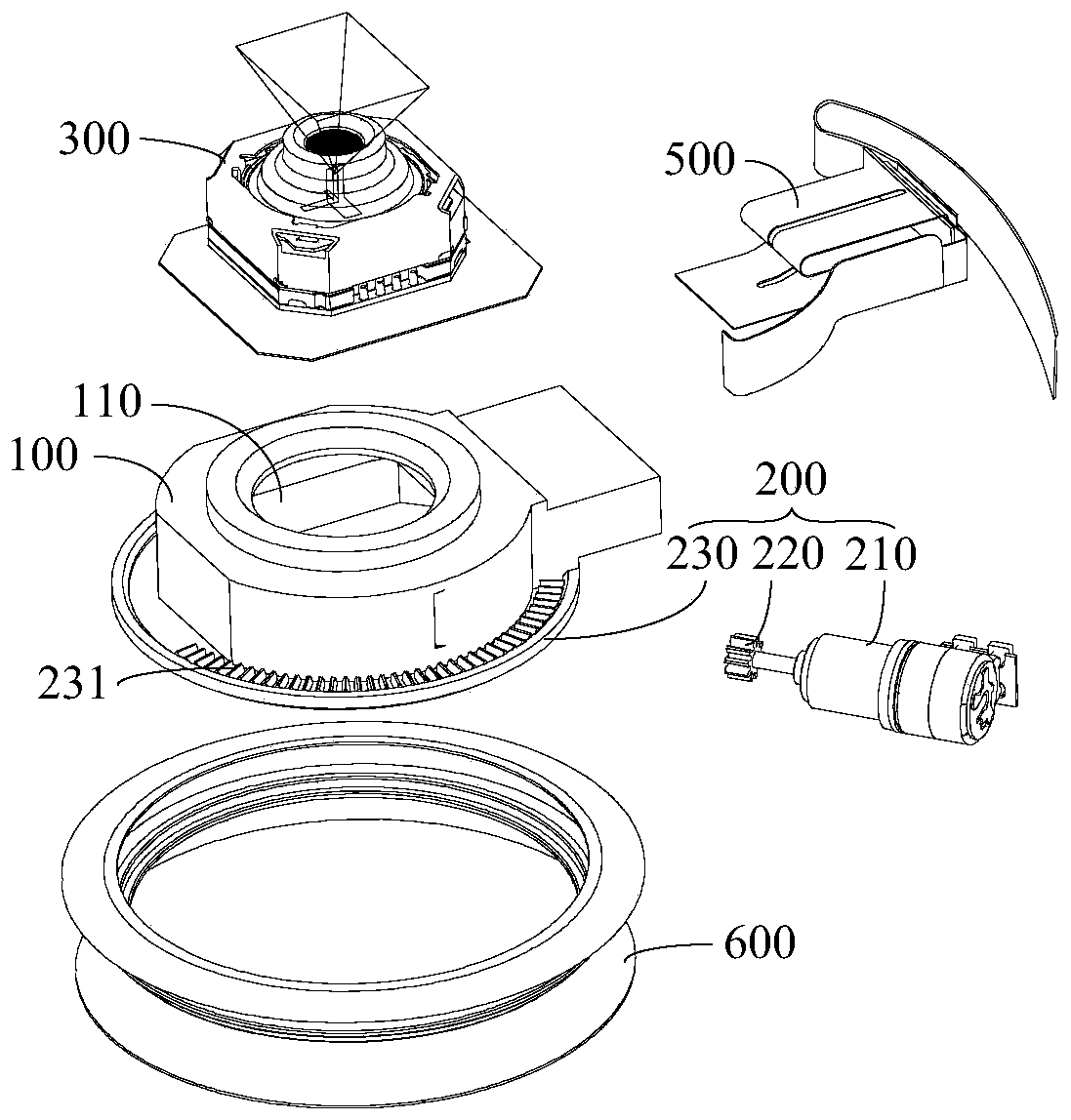
[0028] Please refer to Figure 1-Figure 4 The embodiment of the present invention discloses a camera module, and the disclosed camera module can be applied to electronic equipment. The disclosed camera module includes a module housing 100, a driving mechanism 200, and a mechanical anti-shake camera assembly 300.
[0029] The module housing 100 is a basic component of the camera module, and the module housing 100 can provide an installation basis for other components of the camera module. In the embodiment of the present invention, the module housing 100 has a housing inner cavity 110, the housing inner cavity 110 has an opening, and the opening serves as a retreat. The mechanical anti-shake camera assembly 300 is at least partially disposed in the inner cavity 110 of the housing. The mechanical anti-shake camera assembly 300 includes a camera 310 that can realize image shooting through the opening.
[0030] In the embodiment of the present invention, the module housing 100 is a structure that can rotate, and the mechanical anti-shake camera assembly 300 can rotate with the module housing 100. Under normal circumstances, the electronic device disclosed in the embodiment of the present invention may include a device housing 400, and the module housing 100 is rotatably disposed on the device housing 400, thereby achieving rotation. In a specific embodiment, the module housing 100 can be rotatably disposed on the equipment housing 400 through the bearing 600.
[0031] The drive mechanism 200 is connected to the module housing 100, and the drive mechanism 200 can drive the module housing 100 to rotate. In essence, the drive mechanism 200 can drive the module housing 100 so that the module housing 100 and the mechanical anti-shake camera assembly 300 Rotate together.
[0032] The mechanical anti-shake camera assembly 300 includes a camera 310. In a specific working process, when the entire camera module is tilted due to jitter, the camera 310 can be rotated to compensate for the tilt, thereby achieving anti-shake. Since the camera 310 can rotate, the camera 310 has multiple positions. When the camera 310 is in the first position, the lens axis of the camera 310 coincides with or parallel to the rotation axis of the module housing 100. When the camera 310 is in the first position, the camera module does not tilt, and the camera 310 does not tilt.
[0033] When the camera 310 is in the second position, there is an angle between the lens axis of the camera 310 and the rotation axis of the module housing 100, and in this case, the driving mechanism 200 drives the module housing 100 to rotate. Specifically, the included angle between the lens axis of the camera 310 and the rotation axis of the module housing 100 may be an acute angle. When the camera 310 is in the second position, the camera 310 can be in a tilted state. In this case, the drive module housing 100 can realize the camera 310 to capture images in a larger field of view.
[0034] The camera module disclosed in the embodiment of the present invention is based on the mechanical anti-shake camera assembly 300, and makes full use of the structural feature that the camera 310 of the mechanical anti-shake camera assembly 300 can rotate. The drive mechanism 200 drives the module housing 100 to rotate, thereby driving the The camera 310 in the tilted state rotates again, so that the camera 310 obtains a larger shooting field of view. The camera module does not need to be equipped with a special driving mechanism for driving the camera to rotate in multiple directions. Obviously, the electronic device disclosed in the embodiment of the present invention has a simpler structure and a lower manufacturing cost.
[0035] In the embodiment of the present invention, there may be multiple types of the mechanical anti-shake camera assembly 300. Please refer again image 3 with Figure 4 In a specific implementation, the mechanical anti-shake camera assembly 300 may further include a first bracket 320, the first bracket 320 is at least partially disposed in the housing cavity 110, the camera 310 is at least partially disposed in the housing cavity 110, and the camera 310 can perform shooting through the opening of the housing inner cavity 110.
[0036] In the embodiment of the present invention, the camera 310 and the first bracket 320 are hinged through the first hinge axis 330, and the camera 310 can rotate around the first hinge axis 330. The first bracket 320 is hinged with the module housing 100 through a second hinge axis, and the first bracket 320 rotates around the second hinge axis. The axis of the first hinge axis 330 and the axis of the second hinge axis intersect or are in different planes, that is, the direction in which the camera 310 rotates around the first hinge axis 330 is not consistent with the direction in which the first bracket 320 rotates around the second hinge axis.
[0037] In the specific shooting process, the camera module will tilt due to jitter, which will eventually affect the shooting quality. In the camera module disclosed in the embodiment of the present invention, the camera 310 can rotate relative to the first bracket 320 about the first hinge axis 330, and the first bracket 320 and the module housing 100 are rotatably connected through the second hinge axis, so the camera 310 can Together with the first bracket 320, it rotates relative to the module housing 100 around the second hinge axis. Since the axis of the first hinge axis 330 and the axis of the second hinge axis intersect or are in different planes, the rotation of the camera 310 in the above two directions can compensate for the angular components of the tilt in these two directions caused by the jitter of the camera module. Implement effective anti-shake on the camera module.
[0038] In a more preferred solution, the axis of the first hinge shaft 330 and the axis of the second hinge shaft may be perpendicular to each other. In this case, the inclination angle caused by the shaking of the entire camera module during the shooting process can be easily broken down into separate parts. The two angle components around the direction of the first hinge axis 330 and the direction around the second hinge axis facilitates the angle compensation of the camera 310 during the rotation process.
[0039] The camera 310 is a relatively precise device. In order to avoid damage to the camera 310 due to assembly, in a more preferred solution, the camera module disclosed in the embodiment of the present invention may further include a second bracket 340, and the camera 310 is fixedly connected to the second bracket 340 . The second bracket 340 is hinged with the first bracket 320 through the first hinge shaft 330. In this case, the camera 310 can follow the second bracket 340 to rotate around the first hinge axis 330. In this case, the camera 310 does not need to be directly rotated and connected, and an assembly method that is relatively easy and not easy to damage the camera 310 can be selected between the camera 310 and the second bracket 340.
[0040] The structure of the first bracket 320 may be various. In a more preferred solution, the first bracket 320 may include a bracket body 321 and a first connecting arm 322, and the first end of the first connecting arm 322 is fixedly connected to the bracket body 321. The second end of the first connecting arm 322 is a free end. The second hinge shaft may be fixed on the module housing 100, the bottom end of the first connecting arm 322 may be provided with a second hinge hole 323, and the second hinge shaft is hinged with the second hinge hole 323. The use of the manner in which the first connecting arm 322 is hinged with the module housing 100 through the second hinge shaft is beneficial to reduce the space occupied by the hinge structure. Moreover, the second end of the first connecting arm 322 is a free end, that is, the first connecting arm 322 has a cantilever structure, and the second end of the first connecting arm 322 can extend into the inner cavity 110 of the housing to achieve an articulated connection. Conducive to the miniaturization design of the entire camera module.
[0041] In a more preferred solution, the first bracket 320 may further include a second connecting arm 324, the first end of the second connecting arm 324 is fixedly connected to the bracket body 321, and the second end of the second connecting arm 324 is a free end. The first hinge shaft 330 is fixed on the second bracket 340 or the camera 310, and the second end of the second connecting arm 324 is provided with a first hinge hole 325, and the first hinge hole 325 is hinged with the first hinge shaft 330. The second end of the two connecting arms 324 can extend into the inner cavity 110 of the housing to achieve hinged connection, which is beneficial to the miniaturized design of the entire module bracket. At the same time, the second connecting arm 324 is a cantilever structure, and the first hinge hole 325 is provided at the free end of the second connecting arm 324, so it is easier to realize the hinged assembly through the deformation of the second connecting arm 324.
[0042] In order to improve the stability of the articulation, in a more preferred solution, there may be two first connecting arms 322 and two second connecting arms 324, and the two first connecting arms 322 may be arranged at a pair of angles on both sides of the camera 310. , The two second connecting arms 324 may be distributed on both sides of the camera 310 at another diagonal. In this case, each first connecting arm 322 can be hinged with a second hinge axis, and each second connecting arm 324 can be hinged with a first hinge axis 330, which can undoubtedly improve the balance of rotation support.
[0043] In the embodiment of the present invention, the bracket body 321 is the main body part of the first bracket 320, and the bracket body 321 can ensure that the first connecting arm 322 and the second connecting arm 324 have strong strength. The structure of the stent body 321 can be various. In a more preferred solution, the support body 321 may be provided with a first escape hole 3211. The lens 311 of the camera 310 may be disposed opposite to the first avoiding hole 3211, and the lens 311 of the camera 310 may pass through the first avoiding hole 3211 to take pictures.
[0044] Specifically, the lens 311 of the camera 310 may be completely located in the inner cavity 110 of the housing, or may be located in the first escape hole 3211, of course, it may also extend out of the housing inner cavity 110 through the first escape hole 3211. In order to avoid the opening of the first avoiding hole 3211 being too large, in a more preferred solution, the lens 311 of the camera 310 is located in the first avoiding hole 3211 or extends out of the module housing 100 through the first avoiding hole 3211. In this case, the opening of the first avoiding hole 3211 can be prevented from being too large under the same shooting field of view, or, under the premise that the opening size of the first avoiding hole 3211 is fixed, the above solution can undoubtedly make the shooting field of view of the lens 311 larger . Of course, the lens 311 of the camera 310 needs the first avoiding hole 3211 to form a gap around the lens 311. During the rotation of the camera 310, the existence of the gap can allow the camera 310 to rotate.
[0045] In order to facilitate manufacturing and assembly, in a more preferred solution, the first bracket 320 may be an integral structure. Specifically, the first bracket 320 may be an integral metal structure.
[0046] In a specific anti-shake work process, the camera 310 needs to rotate around the first hinge axis 330 and/or the second hinge axis. There are many ways to drive the camera 310 to rotate. In a more preferred solution, the electronic device disclosed in the embodiment of the present invention may further include a driving mechanism, and the driving mechanism may include a permanent magnet and an electromagnet. Specifically, the electronic device may be equipped with a driving mechanism matching each direction of movement, and there may be multiple types of driving components, such as direct driving by a driving motor, or driving by a driving motor in cooperation with a transmission mechanism. In a more preferred solution, each driving component may include a permanent magnet and an electromagnet, and the movement is driven by the magnetic field force between the electromagnet and the permanent magnet after being energized.
[0047] In order to improve appearance performance, in a more preferred solution, the module housing 100 can be installed with a first cover 700, which is detachably mounted on the module housing 100. In the assembly process, first The first cover 700 is disassembled, and the camera 310 and other components are assembled into the inner cavity 110 of the housing, and then the first cover 700 is installed. The first cover 700 is provided with a second escape hole 710 and an opening in the inner cavity 110 of the housing Located in the second avoiding hole 710. The module housing 100 with the above structure has good assemblability and is convenient for the installation of the camera 310.
[0048] In the embodiment of the present invention, there may be various mechanisms for driving the rotation of the module housing 100, please refer to image 3 In a specific embodiment, the driving mechanism 200 may include a driving motor 210, a driving gear 220, and a circular arc rack 231. The circular arc rack 231 is fixedly connected to the module housing 100, and the driving gear 220 is connected to the circular arc rack. 231 meshes, and the power output shaft of the driving motor 210 is in transmission connection with the driving gear 220. The use of gear mechanism for power transmission has the advantages of relatively stable transmission and high transmission accuracy. The arc rack 231 can ensure that the module housing 100 rotates within a certain angle, and this structure is more suitable for driving the module housing 100 to rotate within a certain angle range. Of course, the arc rack 231 can be replaced by an annular rack.
[0049] Please refer again image 3 In a more preferred solution, the driving mechanism 200 may include a ring structure 230, the ring structure 230 may be arranged around the module housing 100, the ring structure 230 is fixedly connected to the module housing 100, and the ring structure The piece 230 includes a circular arc rack 231. The ring structure 230 can enhance the strength of the module housing 100 and also facilitate the installation of the arc rack 231. In order to facilitate installation, in a more preferred solution, the ring structure 230 and the module housing 100 may be an integral structure.
[0050] Based on the camera module disclosed in the embodiment of the present invention, the embodiment of the present invention discloses an electronic device. The disclosed electronic device includes the aforementioned camera module. The driving mechanism 200 is disposed on the equipment housing 400, and the module housing 100 is rotatably disposed on the equipment housing 400.
[0051] Since the module housing 100 is a rotatable structural member, and the camera 310 needs to be powered during the working process, based on this, a sliding contact power supply method can be adopted to provide power to the camera 310. However, this kind of power supply structure is more complicated and the stability is poor. Based on this, in a more preferred solution, the electronic device disclosed in the embodiment of the present invention may also include a flexible electrical connector 500, and the electronic device may also include For the motherboard in the housing 400, one end of the flexible electrical connector 500 is electrically connected to the motherboard, and the other end of the flexible electrical connector 500 passes through the device housing 400 and is electrically connected to the camera 310. The flexible electrical connector 500 has good deformability, so it can better adapt to the rotation of the module housing 100 and the camera 310. Specifically, the flexible electrical connector 500 may be a flexible circuit board or a flexible cable.
[0052] In a more preferred solution, the flexible electrical connector 500 may be an elastic electrical connector. In this case, the flexible electrical connector 500 has good deformability, and the flexible electrical connector 500 can adapt itself through its own deformation. The rotation of the module housing 100 and the camera 310.
[0053] The electronic devices disclosed in the embodiments of the present invention may be smart phones, tablet computers, e-book readers, wearable devices, etc., and the embodiments of the present invention do not limit the specific types of electronic devices.
[0054] The above embodiments of the present invention focus on the differences between the various embodiments. As long as the different optimization features between the various embodiments are not contradictory, they can be combined to form a better embodiment. Considering the conciseness of the text, here is No longer.
[0055] The foregoing descriptions are merely embodiments of the present invention, and are not intended to limit the present invention. For those skilled in the art, the present invention can have various modifications and changes. Any modification, equivalent replacement, improvement, etc. made within the spirit and principle of the present invention should be included in the scope of the claims of the present invention.

PUM

no PUM

Description & Claims & Application Information

We can also present the details of the Description, Claims and Application information to help users get a comprehensive understanding of the technical details of the patent, such as background art, summary of invention, brief description of drawings, description of embodiments, and other original content. On the other hand, users can also determine the specific scope of protection of the technology through the list of claims; as well as understand the changes in the life cycle of the technology with the presentation of the patent timeline. Login to view more.

Similar technology patents

Classification and recommendation of technical efficacy words

  • Simple structure
  • Low manufacturing cost

Beam expanding optical element, beam expansion method, image display apparatus, and head-mounted display

InactiveUS20070188837A1Reduce color unevennessSimple structureOptical light guidesSubstrate with hologramHead worn displayLight wave
Owner:KONICA MINOLTA INC

Microlithographic projection exposure apparatus

InactiveUS20050068499A1Simple structureReliable and low-maintenance operationProjectorsPhotomechanical exposure apparatusCamera lensPhysics
Owner:CARL ZEISS SMT GMBH

Exercise equipment

InactiveUS6942605B1Low manufacturing costLow price of saleStraight-bar knitting machinesFootwearExercise equipmentPhysical medicine and rehabilitation
Owner:SUKHOVITSKY FELIKS

Hybrid aerial and terrestrial vehicle

ActiveUS20140131507A1Simple designLow manufacturing costConvertible aircraftsMicro-sized aircraftFlight vehicleTerrestrial locomotion
Owner:ILLINOIS INSTITUTE OF TECHNOLOGY

A ceramic insulator device for high voltage capacitor

InactiveCN101546636ALow manufacturing costReasonable structureSuspension/strain insulatorsHigh voltage capacitorsEngineering
Owner:王海龙
Why Eureka
Try Eureka