
Primary feedback control welding power circuit and inverter welder applying primary feedback control welding power circuit

A technology of welding power supply and primary feedback, which is applied in the field of power supply, can solve the problems of affecting welding effect, unstable output current, interference, etc., and achieve the effects of stable load current, improved reliability, and reduced interference

Pending Publication Date: 2020-01-10
珠海市金锐焊接设备科技有限公司
View PDF0 Cites 0 Cited by
  • Summary
  • Abstract
  • Description
  • Claims
  • Application Information

AI Technical Summary

Problems solved by technology

[0003] The general output characteristic of an inverter welding machine is a constant current output. In order to keep the output current constant, current negative feedback is required. In the prior art, the current feedback signal is sampled from the load current, which is usually the output current of the welding electrode. However, the welding electrode The output current is susceptible to interference from the welding environment, resulting in unstable output current and affecting the welding effect

Method used


Image

  • Primary feedback control welding power circuit and inverter welder applying primary feedback control welding power circuit
  • Primary feedback control welding power circuit and inverter welder applying primary feedback control welding power circuit
  • Primary feedback control welding power circuit and inverter welder applying primary feedback control welding power circuit

Examples


Embodiment Construction

[0037] This part will describe the specific embodiment of the present invention in detail, and the preferred embodiment of the present invention is shown in the accompanying drawings. Each technical feature and overall technical solution of the invention, but it should not be understood as a limitation on the protection scope of the present invention.

[0038] In the description of the present invention, it should be understood that the orientation descriptions, such as up, down, front, back, left, right, etc. indicated orientations or positional relationships are based on the orientations or positional relationships shown in the drawings, and are only In order to facilitate the description of the present invention and simplify the description, it does not indicate or imply that the device or element referred to must have a specific orientation, be constructed and operated in a specific orientation, and thus should not be construed as limiting the present invention.

[0039] r...


PUM


Abstract

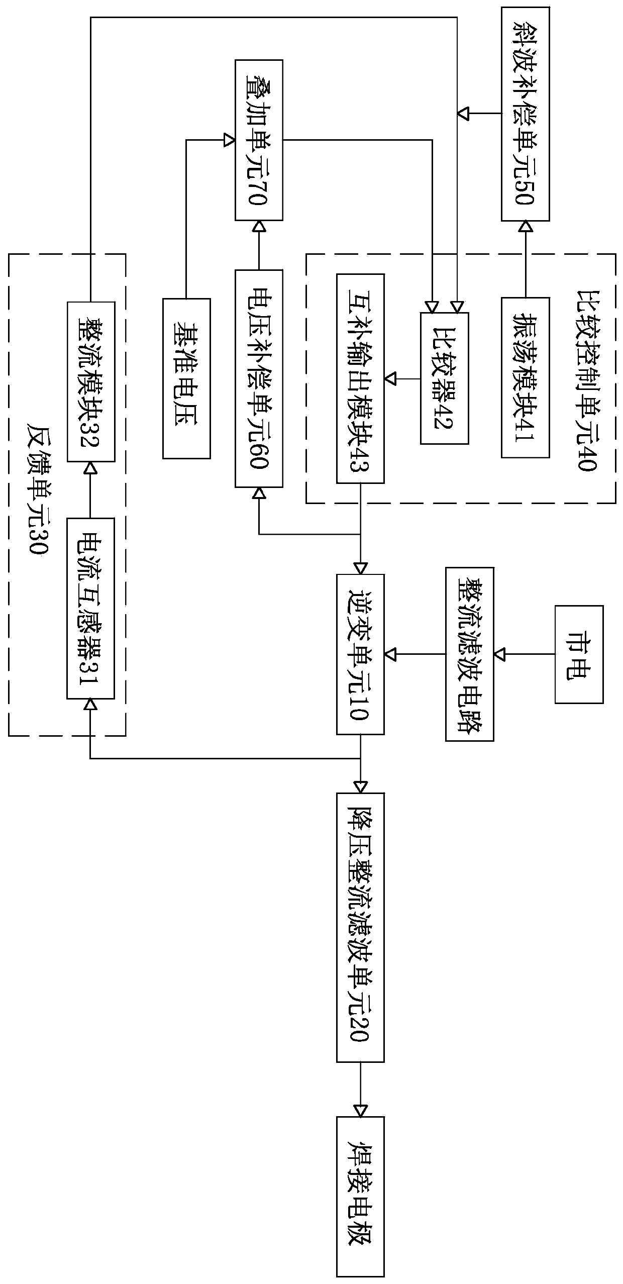
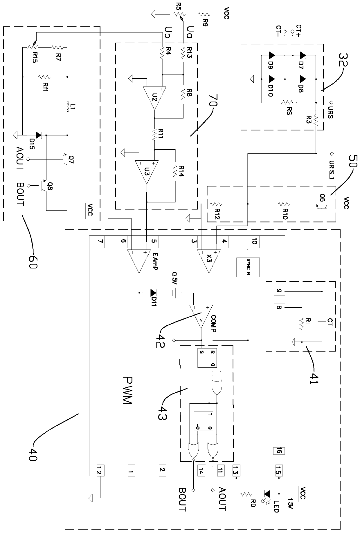
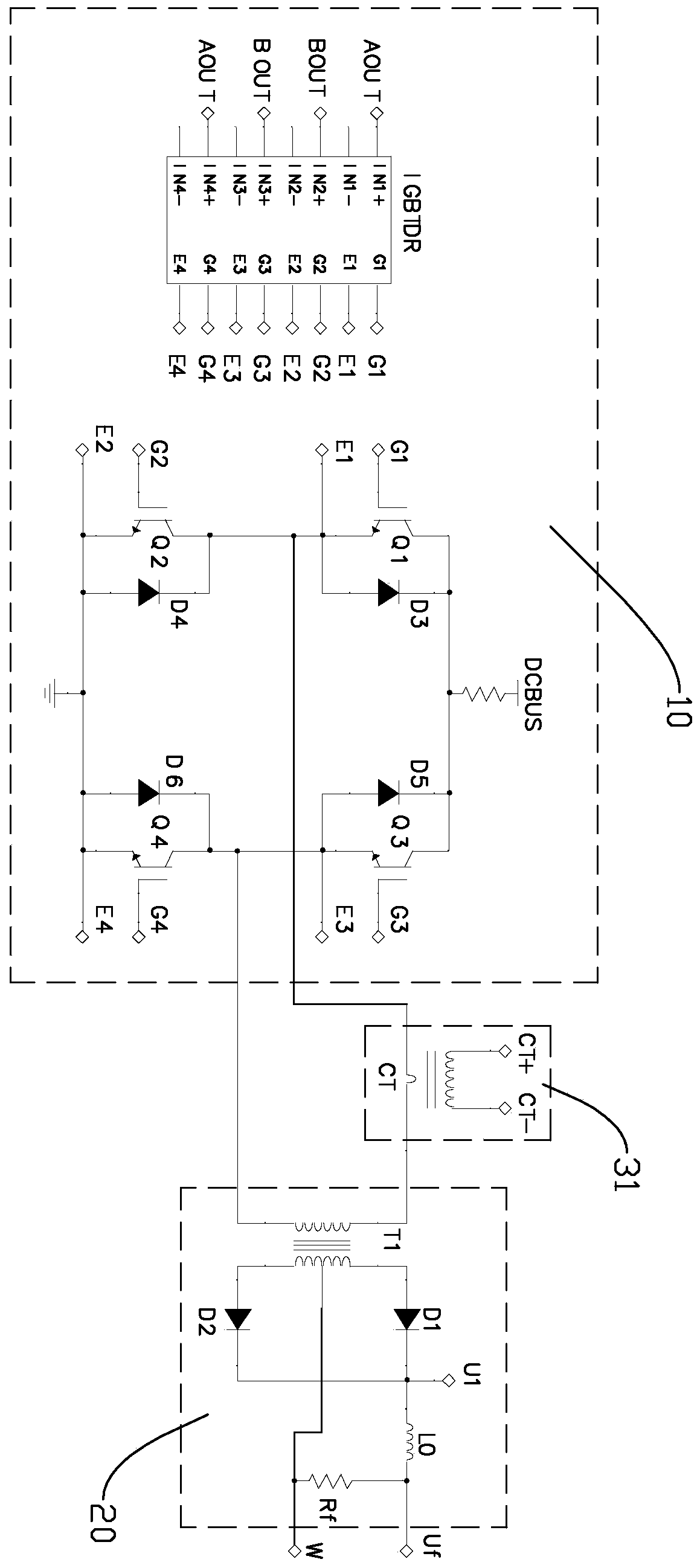
The invention discloses a primary feedback control welding power circuit. The primary feedback control welding power circuit comprises an inverter unit, a voltage-reduction rectification filter unit,a feedback unit and a comparison control unit, wherein the input end of the inverter unit is connected with direct current; the input end of the voltage-reduction rectification filter unit is connected with the output end of the inverter unit, and the output end of the voltage-reduction rectification filter unit is connected with an external welding electrode; the feedback unit is connected with the input end of the voltage-reduction rectification filter unit; and the comparison control unit is provided with a first comparison input end, a second comparison input end and a control output end,the first comparison input end is connected with the feedback unit, the second comparison input end is connected with reference voltage, and the control output end is connected with the control end ofthe inverter unit. According to the primary feedback control welding power circuit and an inverter welder applying the primary feedback control welding power circuit, by means of the manner that feedback signals are obtained from the input end of the voltage-reduction rectification filter unit, interference of the welding environment to the feedback signals can be reduced, and then the final output direct current namely the load current is made to be more stable, and the welding reliability is improved.

Description

technical field [0001] The invention relates to the field of power supplies, in particular to a welding power supply circuit and an electric welding machine using the same. Background technique [0002] As a common processing method to achieve connection, welding has the advantages of good connection performance, high rigidity of the welding structure, and good integrity. Among welding equipment, inverter welding machines are widely used due to their small size, simple operation, and high work efficiency. . [0003] The general output characteristic of an inverter welding machine is a constant current output. In order to keep the output current constant, current negative feedback is required. In the prior art, the current feedback signal is sampled from the load current, which is usually the output current of the welding electrode. However, the welding electrode The output current is susceptible to interference from the welding environment, resulting in unstable output curr...

Claims


Application Information

Patent Timeline
Patent Type & Authority Applications(China)
IPC IPC(8): B23K9/10
CPCB23K9/1043
Inventor 赵以金郭秀星邓长明耿正
Owner 珠海市金锐焊接设备科技有限公司
Learn More