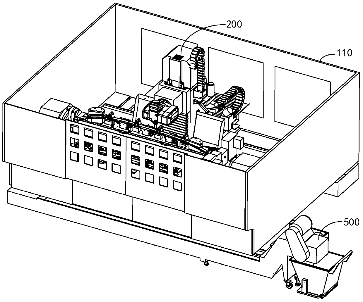
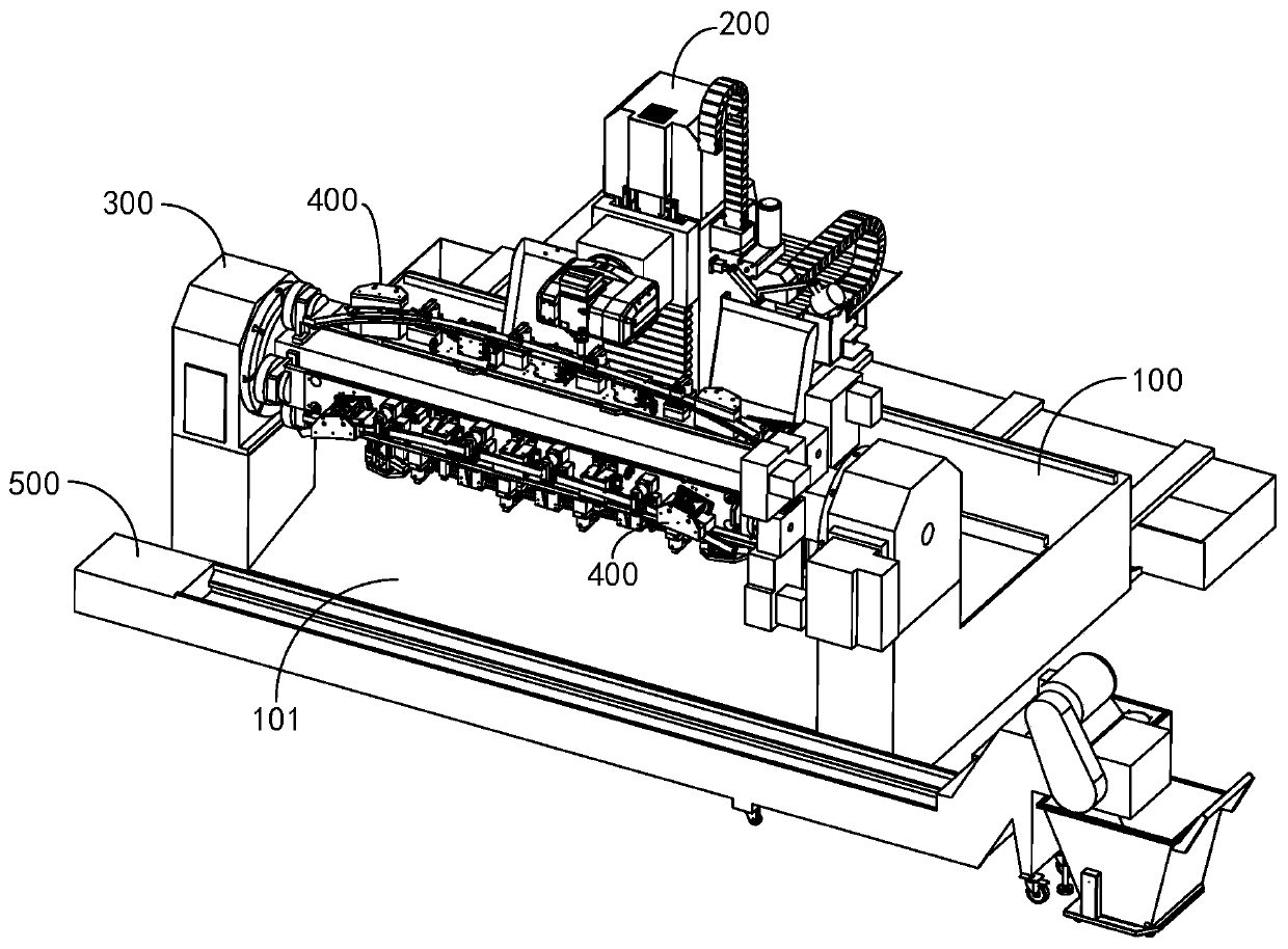
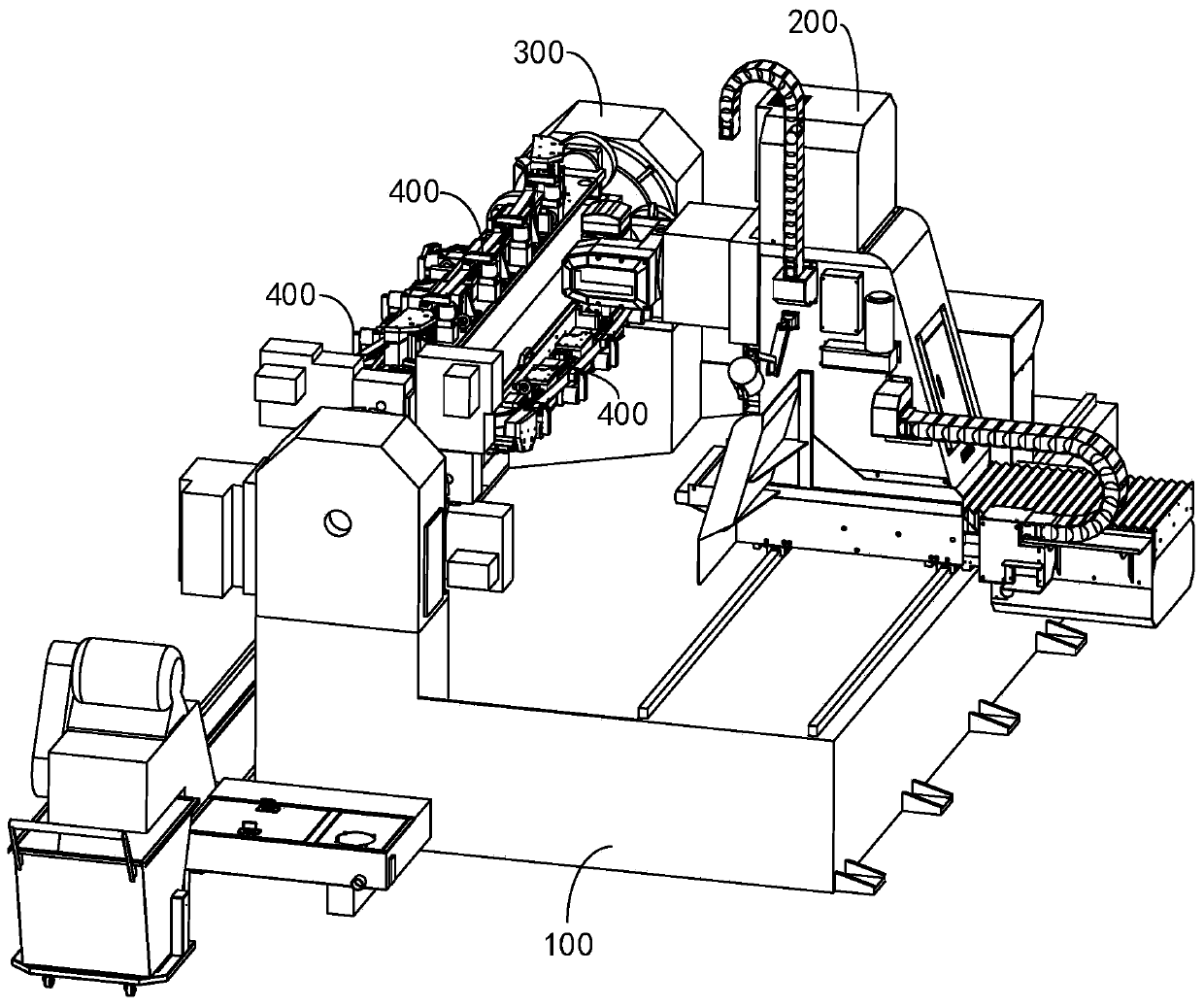
Numerical control machining center

A processing center and processing equipment technology, applied in metal processing equipment, metal processing mechanical parts, manufacturing tools, etc., can solve the problems of low processing efficiency of CNC machining centers, and achieve high processing efficiency, high processing accuracy, and improved utilization. Effect

Pending Publication Date: 2020-01-10
FOSHAN PRATIC CNC SCI & TECH
View PDF0 Cites 1 Cited by
  • Summary
  • Abstract
  • Description
  • Claims
  • Application Information

AI Technical Summary

Problems solved by technology

[0003] The main purpose of the present invention is to propose a numerical control machining center, aiming at solving the technical problem of low machining efficiency of the existing numerical control machining center

Method used


Image

  • Numerical control machining center
  • Numerical control machining center
  • Numerical control machining center

Examples


Embodiment Construction

[0037] The technical solutions in the embodiments of the present invention will be clearly and completely described below in conjunction with the accompanying drawings in the embodiments of the present invention. Obviously, the described embodiments are only a part of the embodiments of the present invention, rather than all the embodiments. Based on the embodiments of the present invention, all other embodiments obtained by those of ordinary skill in the art without creative work shall fall within the protection scope of the present invention.

[0038] It should be noted that if there is a directional indication (such as up, down, left, right, front, back...) in the embodiment of the present invention, the directional indication is only used to explain that it is in a specific posture (as shown in the drawings). If the specific posture changes, the relative positional relationship, movement, etc. of the components below will also change the directional indication accordingly.

[0...


PUM


Abstract

The invention discloses a numerical control machining center. The numerical control machining center comprises a machine table, machining equipment, an engine base and clamps. The machining equipmentis movably arranged on the machine table, and used for machining a workpiece. The engine base is rotationally arranged on the machine table, the engine base and the machining equipment are arranged onthe machine table at an interval, and the engine base is provided with at least two mounting positions. At least two sets of clamps are arranged, and the clamps are mounted on the mounting positionsin a one-to-one correspondence manner. When the engine base rotates to enable one clamp to face the machining equipment, at least one clamp is back to the machining equipment. According to the technical scheme, the numerical control machining center has the advantages of achieving assembly line type machining, being high in machining efficiency and machining precision and the like.

Description

Technical field [0001] The invention relates to the technical field of numerical control processing, in particular to a numerical control processing center. Background technique [0002] In the current CNC machining center, when the workpiece is processed, the workpiece is usually fixed on the processing table by a fixture, and then the workpiece is processed by the processing equipment. Because the current CNC machining center has a unique number of fixtures, the processing equipment needs to be in a shutdown state when the workpiece is loaded and unloaded, which results in wasted processing time of the processing equipment and reduced the processing efficiency of the CNC processing center. Summary of the invention [0003] The main purpose of the present invention is to propose a numerical control machining center, which aims to solve the technical problem of low processing efficiency of the existing numerical control machining center. [0004] In order to achieve the above objec...

Claims


Application Information

Patent Timeline
Patent Type & Authority Applications(China)
IPC IPC(8): B23Q3/08B23Q11/08B23Q5/22B23Q1/25
CPCB23Q1/25B23Q3/08B23Q5/22B23Q11/08
Inventor 李爱军沈成辉李寿超何旭婷彭刚
Owner FOSHAN PRATIC CNC SCI & TECH
Why Eureka
Try Eureka