

A pet cold air intake with resonant cavity
A technology of air inlet and resonant cavity, which is applied in the arrangement of cooling combination of power unit, power unit, vehicle components, etc., can solve the problems of long pipeline, complicated process, occupying the length of pipeline, etc., and achieve the effect of noise reduction , The process is simple and the effect of reducing the cost of the pipeline
- Summary
- Abstract
- Description
- Claims
- Application Information
AI Technical Summary
Problems solved by technology
Method used
Image

Examples
Embodiment Construction
[0016] Describe technical scheme of the present invention in detail below in conjunction with accompanying drawing:
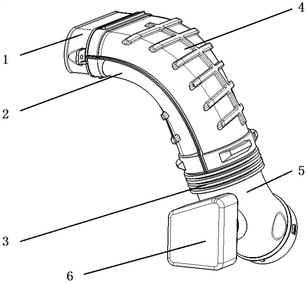
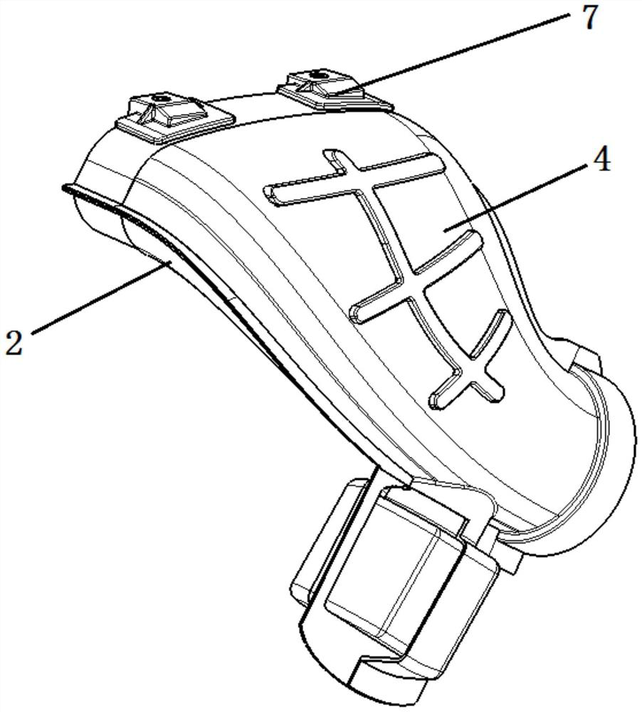
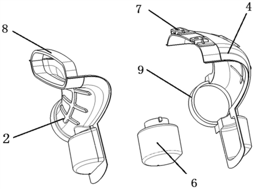
[0017] refer to figure 2 , image 3 , a PET cold air inlet with a resonant cavity, the main pipeline of the air inlet is all made of PET material, including a PET upper part 4 and a PET lower part 2, and a cavity shell wrapping a resonant cavity 6 is arranged between the PET upper part and the PET lower part , PET upper part and PET lower part are welded and fixed, and the resonant cavity is covered in the cavity shell, and the resonant cavity and the cavity shell are closely matched, so that the resonant cavity cannot move in the pipeline.
[0018] The front end of the PET upper part 4 is preset with a fixed structure and a fixed nut is pre-embedded on the fixed structure, the air inlet pipeline is fixed on the front frame by bolts, and the rear end of the air inlet pipeline is fastened to the air filter.
[0019] In order to ensure easy assembly, the front...
PUM
 Abstract
Description
Claims
Application Information