Device for collecting and recovering surgical tools

A scalpel, jacking device technology, applied in the direction of surgery, conveyor control device, application, etc., to achieve the effect of convenience

Active Publication Date: 2020-01-10
张秀杰
View PDF9 Cites 5 Cited by
  • Summary
  • Abstract
  • Description
  • Claims
  • Application Information

AI Technical Summary

Problems solved by technology

[0003] The purpose of this application is to provide a device for receiving and retrieving surgical knives, which can realize the supply of surgical knives and the recovery of surgical knives

Method used


Image

  • Device for collecting and recovering surgical tools
  • Device for collecting and recovering surgical tools
  • Device for collecting and recovering surgical tools

Examples


Embodiment 1

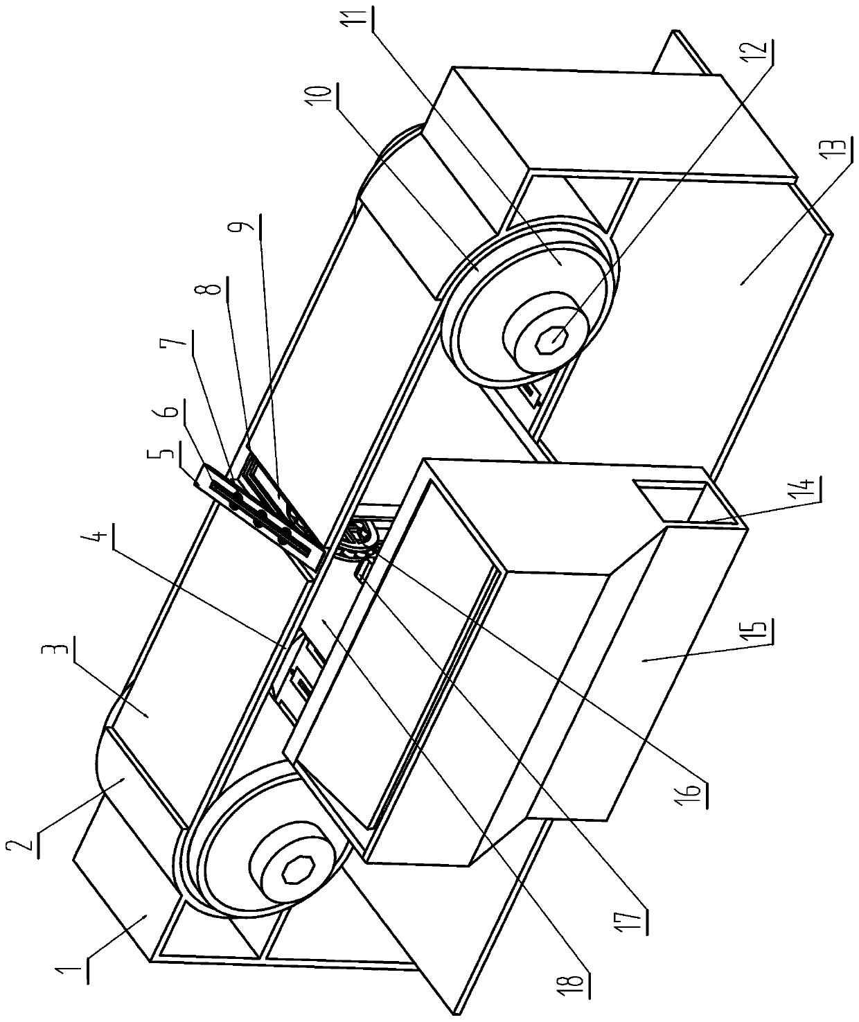
[0028] A device for receiving and recovering surgical knives, comprising a base 13, on both sides of the base 13, a bracket 1 perpendicular to the base 13 is installed, and the bracket 1 is symmetrically arranged on both sides of the base 13, inside the bracket 1 An arc-shaped connecting part 2 extending inward is provided, and an arc-shaped limiting part 3 is welded on the inner surface of the arc-shaped connecting part 2, and the opposite arc-shaped limiting part 3 is connected at the bottom, and the oppositely arranged limiting part 3 There is a space for a single conveyor belt groove 9 on the conveyor belt 4 to be exposed at the top; a transmission wheel 11 is arranged inside the arc-shaped limiting part 3, and the transmission wheels 11 are connected by the conveyor belt 4, and several conveyor belts are distributed on the conveyor belt 4. The conveyor belt trough 9 for the installation and placement of the feeding plate 5 is processed with a stepped part 8 inside the conv...

Embodiment 2

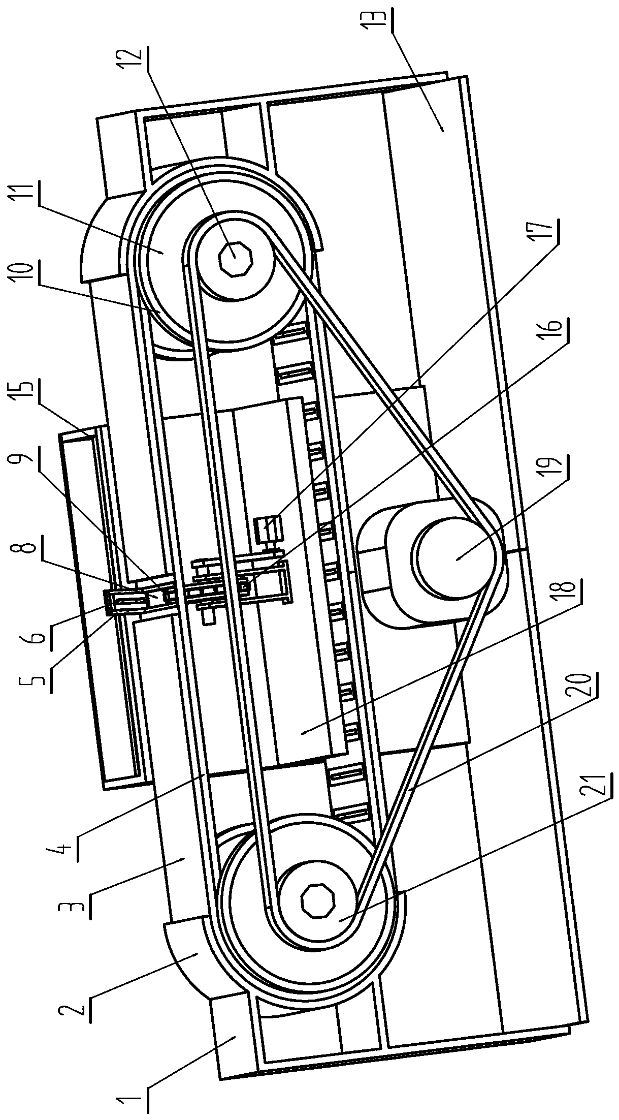
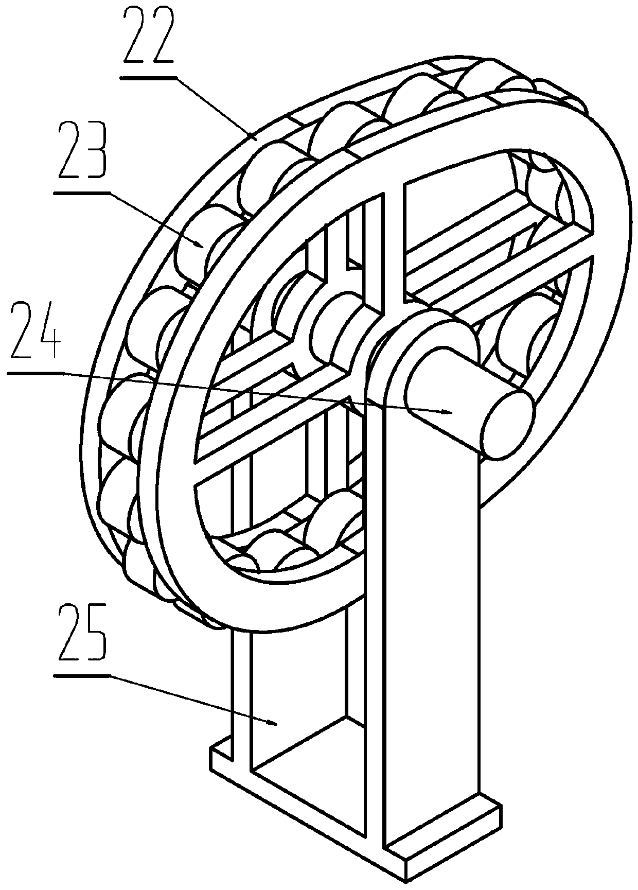
[0030] A device for receiving and retrieving surgical knives, the transmission wheel 11 is provided with transmission guides 10 on both sides of the contact position of the conveyor belt body 4, and the transmission guides 10 are annular bumps protruding from the transmission wheel 11; Described jacking device 16 comprises two cam frame bodies 22 that are arranged in parallel, is processed with the blind hole that is connected with roller body 23 on adjacent cam frame body 22 and is connected with roller body 23 by bearing structure in the blind hole, and roller The outer surface of body 23 is higher than the outer surface of cam frame body 22; Described cam frame body 22 is installed on the cam bracket 25 by cam drive shaft 24, and cam bracket 25 is fixed on the supporting partition 18; Described feeding plate 5 comprises The upper plate 26 and the lower plate 30 of the rectangular plate structure, the width and thickness of the upper plate 26 are the same as the width and thi...

Embodiment 3

[0032] A device for receiving and recovering surgical knives, wherein the feeding plate 5 is processed with a placement groove 6 passing through the upper plate body 26 and the lower plate body 30, and the placement groove 6 includes a longitudinal section processed on the upper plate body 26 It is a trapezoidal trapezoidal notch 28, a rectangular notch 29 that is processed on the lower plate body 30 and communicates with the trapezoidal notch 28; the two sides of the trapezoidal notch 28 are provided with a handle 7, and the handle 7 is in the trapezoidal notch. 28 Counterbore structure processed on both sides. The structures and connections of the remaining parts are the same as those described in any of the foregoing embodiments.


PUM


Abstract

The invention discloses a device for collecting and recovering surgical tools, and belongs to the field of surgical auxiliary devices. The device is used for picking and placing the surgical tools comprises a base with supports. Arc-shaped connecting parts are arranged on the supports correspondingly and are connected with arc-shaped limiting parts. Conveying wheels are arranged in the arc-shapedlimiting parts. A gap for a conveying belt to pass through is reserved between the conveying wheels and the arc-shaped limiting parts. The conveying wheels are connected with synchronous wheels, a synchronous belt and a driving motor through driving shafts. The synchronous belt is provided with a plurality of conveying belt groove bodies. A feeding plate hinged to one end of the conveying belt groove body is placed in each conveying belt groove body. A supporting partition plate is arranged on the base. An ejecting device driven by an ejecting power mechanism is installed on the supporting partition plate. The surgical tools can be supplied and recovered according to a designated plan in the surgery process, and the problems of surgery risks and tool picking and placing inconvenience probably caused by manual transferring are reduced.

Description

technical field [0001] The present application belongs to the field of surgical auxiliary devices, and in particular relates to a device for receiving and recovering surgical knives. Background technique [0002] The scalpel is a commonly used instrument in surgery. The traditional transfer method is to pass the blunt end of the scalpel handle to the operator after washing hands. However, the above process has certain safety hazards and is likely to cause sharp injuries. In order to avoid the above problems, the instruments during the operation are generally placed in the curved plate for transmission, but during the operation, the knives placed in the curved plate are difficult to pick up when the operator holds rubber gloves. How to realize the pick-and-place and recovery of knives during the operation has become a technical problem that the industry needs to solve. Based on the above problems, the applicant provides the following technical solutions and devices. Conten...

Claims


Application Information

Patent Timeline
IPC IPC(8): B65G47/38B65G15/30B65G43/08A61B50/20A61B50/36A61B90/00
CPCA61B50/20A61B50/362A61B90/08A61B2090/0805B65G15/30B65G43/08B65G47/38B65G2201/02
Inventor 张秀杰
Owner 张秀杰
Why Eureka
Try Eureka