Long and thin pipe deep hole inner wall chromeplating self-centering clamping cap

A slender tube and self-centering technology, applied in the electrolysis process, electrolysis components, etc., can solve the problems of product performance degradation and the influence of the uniformity of the thickness of the chrome plating layer, etc., to achieve improved performance, high economic benefits and social value, Positioning Reliable Effects

Pending Publication Date: 2020-01-10
CHONGQING JIANSHE IND GRP
View PDF0 Cites 2 Cited by
  • Summary
  • Abstract
  • Description
  • Claims
  • Application Information

AI Technical Summary

Problems solved by technology

[0004] Since the inner hole of the upper and lower cap clamping parts of the current chrome plating device and the outer circle of the slender tube clamping part are clearance fit, with the difference in the size of the outer circle of the slender tube assembly part, and the upper and lower cap mounting The inner hole of the clip part is constantly worn during use, and the coaxiality error between the axis of the inner hole of the slender tube and the axis of the anode steel wire will become larger and larger, which will greatly affect the uniformity of the thickness of the chrome-plated layer on the inner wall of the slender tube, resulting in Product performance decline

Method used


Image

  • Long and thin pipe deep hole inner wall chromeplating self-centering clamping cap
  • Long and thin pipe deep hole inner wall chromeplating self-centering clamping cap
  • Long and thin pipe deep hole inner wall chromeplating self-centering clamping cap

Examples


Embodiment Construction

[0046] Embodiments of the present invention will be described in further detail below in conjunction with the accompanying drawings.

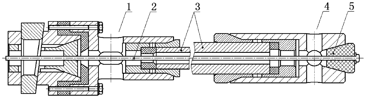
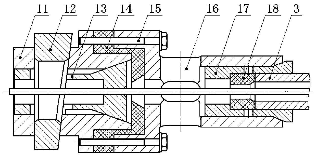
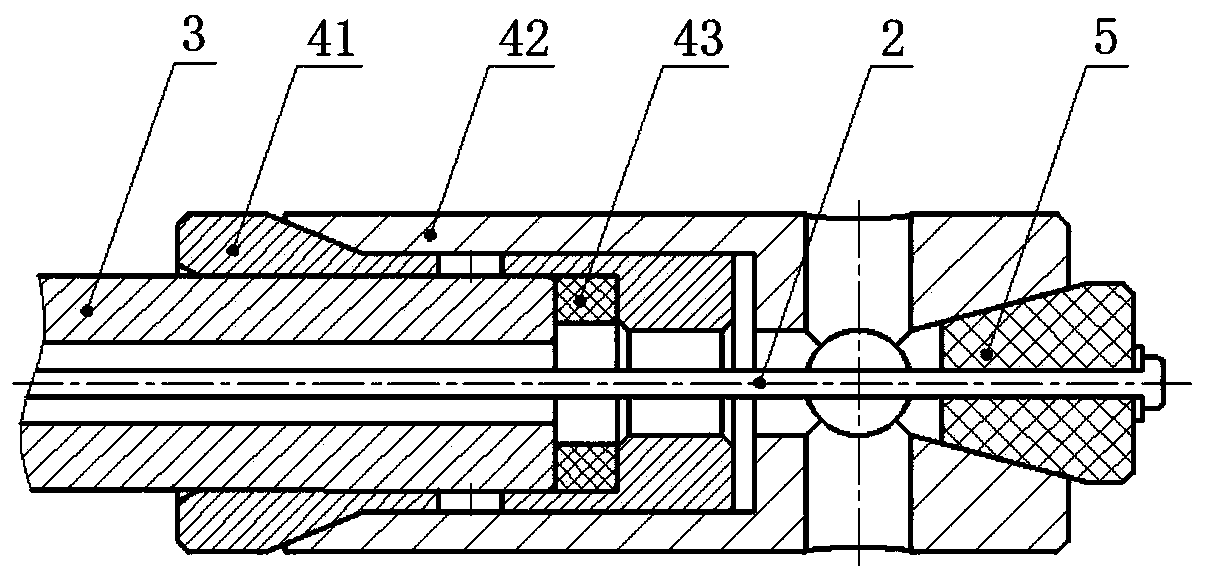
[0047] see Figure 1-Figure 11, a chrome-plated self-centering clamping cap on the inner wall of the deep hole of the slender tube. The inner wall of the deep hole of the slender tube is chrome-plated. The clamping cap includes two parts: an upper cap 1 and a lower cap 4. The main structure is a structure of revolution, the upper cap 1 and the lower cap 4 are clamped with a slender tube 3 (workpiece), the upper cap 1, the lower cap 4 and the central hole of the slender tube 3 are pierced There are anode steel wire 2, when chrome plating, the upper cap 1 and the lower cap 4 are respectively installed together with the two ends of the slender tube 3 through hole shaft cooperation, and the axis of the anode steel wire and the axis of the slender tube can be aligned on the same line through the clamping cap. On a straight line, make sure the two a...


PUM


Abstract

The invention discloses a long and thin pipe deep hole inner wall chromeplating self-centering clamping cap. The long and thin pipe deep hole inner wall chromeplating self-centering clamping cap comprises an upper cap, a lower cap, a long and thin pipe and an anode steel wire. The upper cap comprises an anode steel wire locking mechanism body, an anode steel wire locking mechanism spring jacket, awedge-shaped locking block, an insulation gasket, an upper cap body and an upper cap self-centering spring jacket. The lower cap comprises a lower cap body and a lower cap self-centering spring jacket. The anode steel wire locking mechanism spring jacket is arranged in the anode steel wire locking mechanism body. The wedge-shaped locking block is arranged on the front portion of the anode steel wire locking mechanism body, and the upper cap body is arranged at the rear end of the anode steel wire locking mechanism body. The insulation gasket is arranged between the anode steel wire locking mechanism body and the upper cap body, and the upper cap self-centering spring jacket is arranged in the rear end of the upper cap body. The lower cap self-centering spring jacket is arranged in the front end of the lower cap body, the rear end of the lower cap body is sleeved with the anode steel wire limiting insulation block, and the anode steel wire is limited and self-centered. The long and thin pipe deep hole inner wall chromeplating self-centering clamping cap has a self-centering function, and decentration of the anode steel wire in the long and thin pipe is avoided.

Description

technical field [0001] The invention belongs to the technical field of mechanical devices for electroplating, and in particular relates to a chrome-plated self-centering clamping cap on the inner wall of a deep hole of a slender tube. Background technique [0002] In order to improve the wear resistance and ablation resistance of the inner wall of the deep hole of a slender tube under high pressure, high speed and high temperature environment, it is necessary to chrome-plate the inner wall of the deep hole. [0003] At present, the clamping scheme adopted for chrome plating on the inner wall of a deep hole of a slender tube is: the two ends of a slender tube are respectively clamped by the upper cap and the lower cap, and the special anode steel wire coated with other various metal materials is sequentially Insert the center hole of the lower cap, the inner hole of the slender tube and the center hole of the upper cap, straighten and tighten the anode steel wire under the ac...

Claims


Application Information

Patent Timeline
Patent Type & Authority Applications(China)
IPC IPC(8): C25D7/04C25D17/06C25D5/02
CPCC25D5/02C25D7/04C25D17/06
Inventor 向家云刘榜劳郭阳张必良吉陵刘兵刘元扩
Owner CHONGQING JIANSHE IND GRP
Why Eureka
Try Eureka