A shielded water-cooled permanent magnet high-speed well pump motor

A water-cooled, pump motor technology, used in electromechanical devices, electrical components, electric components, etc., can solve the problems of complex structure, less than ideal, slow flow rate, etc.

Active Publication Date: 2021-09-14
浙江浙水工贸有限公司
View PDF11 Cites 0 Cited by
  • Summary
  • Abstract
  • Description
  • Claims
  • Application Information

AI Technical Summary

Problems solved by technology

[0002] Some pump motors for wells are simply placed in water to dissipate heat, and some use the content disclosed in the prior application CN201821221539. The flow of water can be achieved by setting threads and impeller blades on the outer wall of the rotor. In actual use, it is found that the flow rate is slow and not ideal, and impurities such as sediment in the water are easy to enter the motor, causing internal wear; A high head requires a higher speed, but with the increase of the speed, the running stability of the motor in the water pump will decrease, which will affect the performance of the water pump. Therefore, how to effectively improve the stability of the motor during operation is particularly important; therefore, it is necessary to further improvement of

Method used


Image

  • A shielded water-cooled permanent magnet high-speed well pump motor
  • A shielded water-cooled permanent magnet high-speed well pump motor
  • A shielded water-cooled permanent magnet high-speed well pump motor

Examples


Embodiment 1

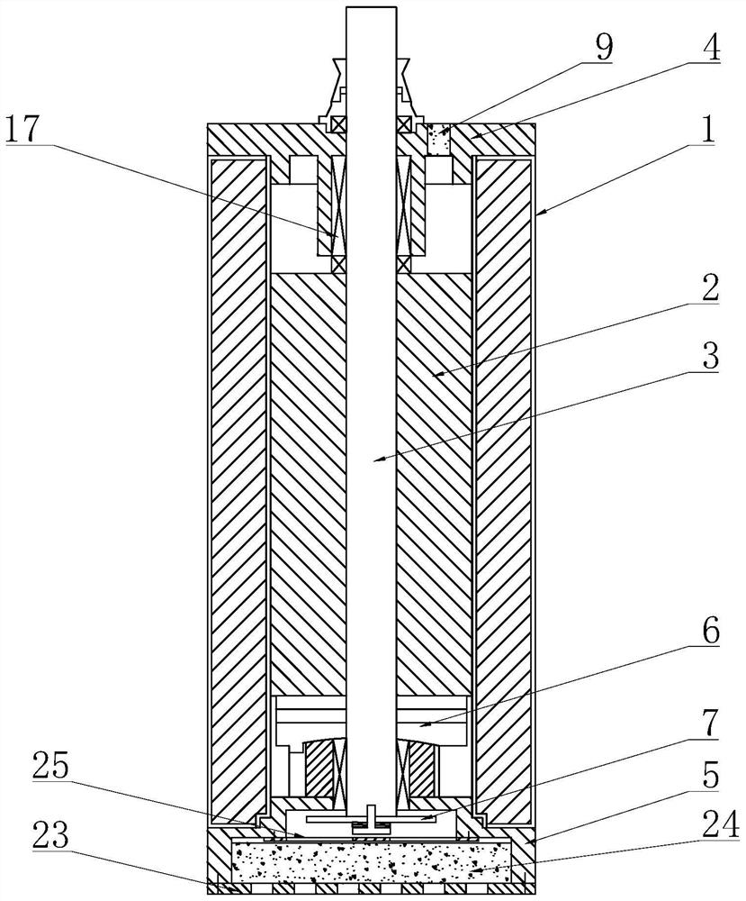
[0055] A shielded water-cooled permanent magnet high-speed well pump motor, including a casing 1, a stator, a rotor 2 and a rotating shaft 3, the rotor 2 is fixed on the rotating shaft 3, and the two ends of the casing 1 are respectively provided with an upper end cover 4 and a lower end cover 5. The upper end cover 4 is provided with an upper shaft hole adapted to the rotating shaft 3, and the lower end cover 5 is provided with a lower shaft hole adapted to the rotating shaft 3. It is characterized in that: the casing 1 is an inner and outer double-layer structure. A shielding chamber is formed between the layers of casings 1, the stator is installed in the shielding chamber, and the shielding chamber is filled with resin, an axial thrust assembly 6 is provided between the lower end of the rotor 2 and the lower end cover 5, and the lower end of the rotating shaft 3 is also provided with There is a pumping impeller 7 located on the outside of the lower end cover 5, a flow guide...

Embodiment 2

[0066] Compared with Embodiment 1, the difference is that the structure of the filter assembly is different, and it can automatically perform blockage removal and anti-blockage control. The specific content is as follows:

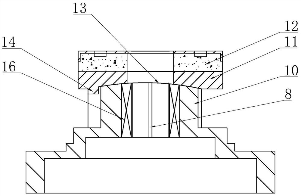
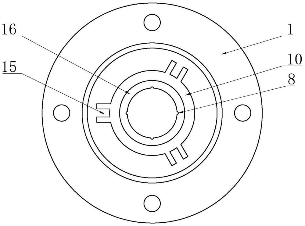
[0067] The filter assembly includes an outer frame 100 and a gear box 101 installed in the outer frame 100. The upper transmission shaft 102 and the lower transmission shaft 103 are respectively connected to the gear box 101, and there is also a gear box for connecting the upper transmission shaft 102 and the lower transmission shaft. The reduction gear set of the transmission shaft 103, the upper transmission shaft 102 and the rotating shaft 3 are connected by a floating coupling 104, and the bottom end of the rotating shaft 3 is provided with a shaft for controlling the axial conflict or separation between the floating coupling 104 and the rotating shaft 3 The first clutch device, the lower section of the outer frame 100 is a filter area, the periphery of ...


PUM


Abstract

The invention discloses a shielded water-cooled permanent magnet high-speed well pump motor, which has good cooling and heat dissipation effects, good operation stability and long service life. The key points of the technical scheme are a shielded water-cooled permanent magnet high-speed well pump The motor includes a casing, a stator, a rotor and a rotating shaft. The rotor is fixed on the rotating shaft. The two ends of the casing are respectively provided with an upper end cover and a lower end cover. The upper end cover is provided with an upper shaft hole adapted to the rotating shaft. There is a lower shaft hole adapted to the rotating shaft. The casing is an inner and outer double-layer structure. A shielding cavity is formed between the two layers of casings. The stator is installed in the shielding cavity, and the shielding cavity is filled with resin. The lower end of the rotor and the There is an axial thrust assembly between the lower end covers, the lower end of the shaft is also provided with a pumping impeller located outside the lower end cover, a guide channel is provided in the lower shaft hole, a water flow channel is provided outside the rotor, and a water passage is provided on the upper end cover. The water outlet, and the guide channel, the water flow channel and the water outlet are connected in sequence, and the invention is applicable to the technical field of motors.

Description

technical field [0001] The invention belongs to the technical field of motors, in particular to a shielded water-cooled permanent magnet high-speed pump motor for wells. Background technique [0002] Some pump motors for wells are simply placed in water to dissipate heat, and some use the content disclosed in the prior application CN201821221539. The flow of water can be achieved by setting threads and impeller blades on the outer wall of the rotor. In actual use, it is found that the flow rate is slow and not ideal, and impurities such as sediment in the water are easy to enter the motor, causing internal wear; A high head requires a higher speed, but with the increase of the speed, the running stability of the motor in the water pump will decrease, which will affect the performance of the water pump. Therefore, how to effectively improve the stability of the motor during operation is particularly important; therefore, it is necessary to further improvement of. Contents ...

Claims


Application Information

Patent Timeline
Patent Type & Authority Patents(China)
IPC IPC(8): H02K5/20H02K9/19H02K9/26H02K7/14
CPCH02K5/20H02K7/14H02K9/19H02K9/26
Inventor 张文敏
Owner 浙江浙水工贸有限公司
Why Eureka
Try Eureka