
Electric chuck based on bevel gear

A technology of bevel gears and bevel teeth, which is applied in the field of electric chucks, can solve problems such as high repeatability and high labor intensity, and achieve the effects of compact structure, reduced labor costs, and improved work efficiency

Pending Publication Date: 2018-05-11
焦彬彬
View PDF0 Cites 0 Cited by
  • Summary
  • Abstract
  • Description
  • Claims
  • Application Information

AI Technical Summary

Problems solved by technology

[0002] With the continuous improvement and development of industrial technology, the replacement of complex and new labor by automation equipment is the only way for a country to become a powerful country. At present, the existing pipe cutting equipment in the laser cutting industry is still generally placed on the pipe cutting machine manually. And manually manipulate the chuck to clamp the pipe fittings on the chuck, which is labor-intensive and highly repeatable

Method used


Image

  • Electric chuck based on bevel gear
  • Electric chuck based on bevel gear
  • Electric chuck based on bevel gear

Examples


Embodiment Construction

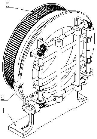
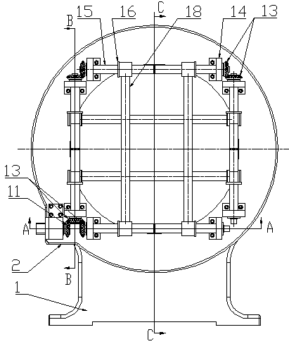
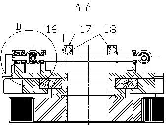
[0008] An electric chuck based on bevel gears, consisting of 1 base, 2 rotating discs, 3 crossed roller guide rails, 4 connecting discs, 5 synchronous pulleys, 6 motors, 7 end covers, 8 bearing blocks 1, 9 bearings, 10 Sleeve, 11 bevel gear shaft, 12 round nut I, 13 bevel gear, 14 bearing housing II, 15 screw shaft, 16 screw nut, 17 optical shaft seat, 18 optical axis, 19 round nut II, characterized in that : 2 Rotating discs are positioned on the inner wall of 3 cross roller guide rails and fixed on the inner wall of 3 cross roller guide rails, the outer wall of 3 cross roller guide rails is fixed in the inner hole of 1 base, 4 one side of the connecting disc is fixed on 3 cross roller guide rails On the inner wall of the guide rail, 5 synchronous pulleys are fixed on one side, 8 bearing housings I and 14 bearing housings II are fixed on 2 rotating discs, 6 motors are installed on 7 end covers, 7 end covers are fixed on 8 bearing housings I, two 9 bearings are installed in th...


PUM


Abstract

Provided is an electric chuck based on a bevel gear. The electric chuck is composed of a base, a rotary disk, crossed roller guide rails, a connecting disk, a synchronous pulley, a motor, an end cover, a bearing seat I, bearings, a sleeve, a bevel gear shaft, a circular nut I, the bevel gear, a bearing seat II, lead screw shafts, lead screw nuts, plain shaft seats, light shafts and a circular nutII and characterized in that the rotary disk is located at the inner walls of the crossed roller guide rails and fixed at the inner walls of the crossed roller guide rails; the bevel gear of the bevelgear shaft is meshed with the bevel gear to transfer power; the lead screw shafts are locked by the bevel gear and a bearing installed in the bearing II through the circular nut I; each lead screw shaft is divided into two symmetrical sections; the rotary direction of each screw is divided into leftward-rotary direction and rightward-rotary direction; the lead screw nuts are installed on the leadscrew shafts; the plain shaft seats are mounted on the lead screw nuts; the plain shafts are installed in holes of the plain shaft seats; and a steel pipe on a laser cutting machine can be clamped tightly and loosened when the four plain shafts approach and depart.

Description

technical field [0001] The invention relates to an electric chuck based on a bevel gear, which belongs to the field of laser cutting mechanical equipment. Background technique [0002] With the continuous improvement and development of industrial technology, the replacement of complex and new labor by automation equipment is the only way for a country to become a powerful country. At present, the existing pipe cutting equipment in the laser cutting industry is still generally placed on the pipe cutting machine manually. And manually operate the chuck to clamp the pipe fittings on the chuck, which is labor-intensive and highly repeatable. Therefore, there is an urgent need for a chuck device that reduces the repetitive labor of personnel and clamps the pipe fittings in an electric manner. Contents of the invention [0003] To solve the above disadvantages, the present invention provides an electric chuck based on bevel gears. [0004] The present invention is achieved thr...

Claims


Application Information

Patent Timeline
Patent Type & Authority Applications(China)
IPC IPC(8): B23K26/70
CPCB23K26/702
Inventor 焦彬彬
Owner 焦彬彬
Learn More