Sand layer compacting device

A compaction device and sandy soil layer technology, which is applied in soil protection, roads, construction, etc., can solve the problems that the road roller is large in size, cannot be compacted in small areas, and cannot be used in narrow places, etc., to achieve convenient movement, The effect of moderate volume and convenient transportation

Inactive Publication Date: 2020-01-10
毛照丰
View PDF6 Cites 2 Cited by
  • Summary
  • Abstract
  • Description
  • Claims
  • Application Information

AI Technical Summary

Problems solved by technology

[0005] 2. The volume of the roller is too large to compact small areas;
[0006] 3. The road roller is only suitable for wider places and cannot be used in narrow places

Method used


Image

  • Sand layer compacting device
  • Sand layer compacting device
  • Sand layer compacting device

Examples


specific Embodiment approach 1

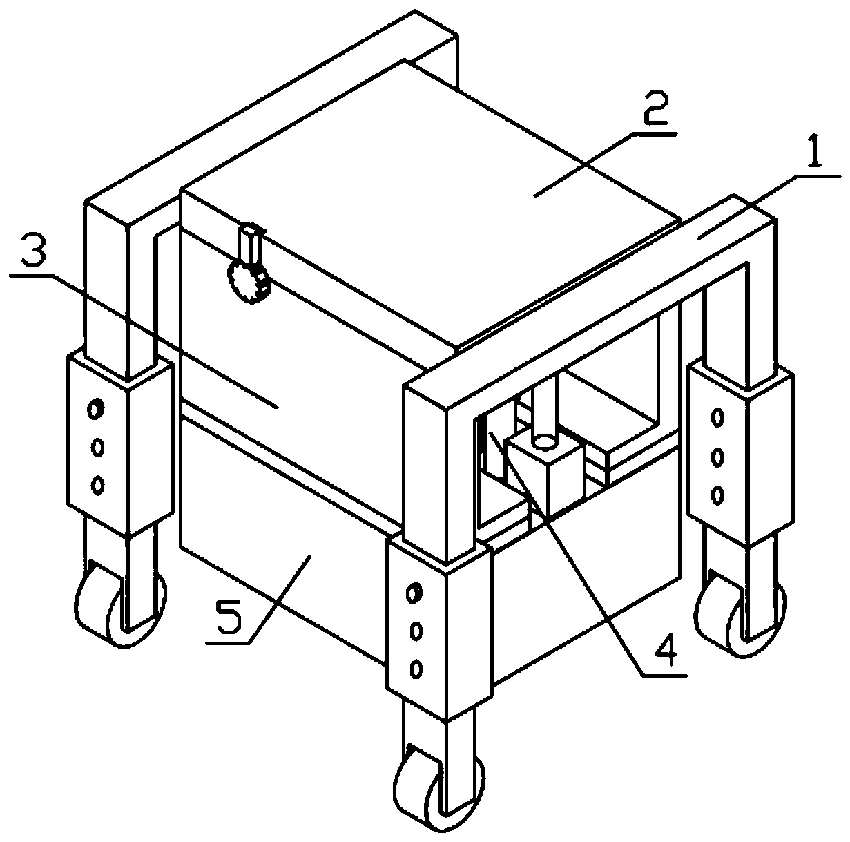
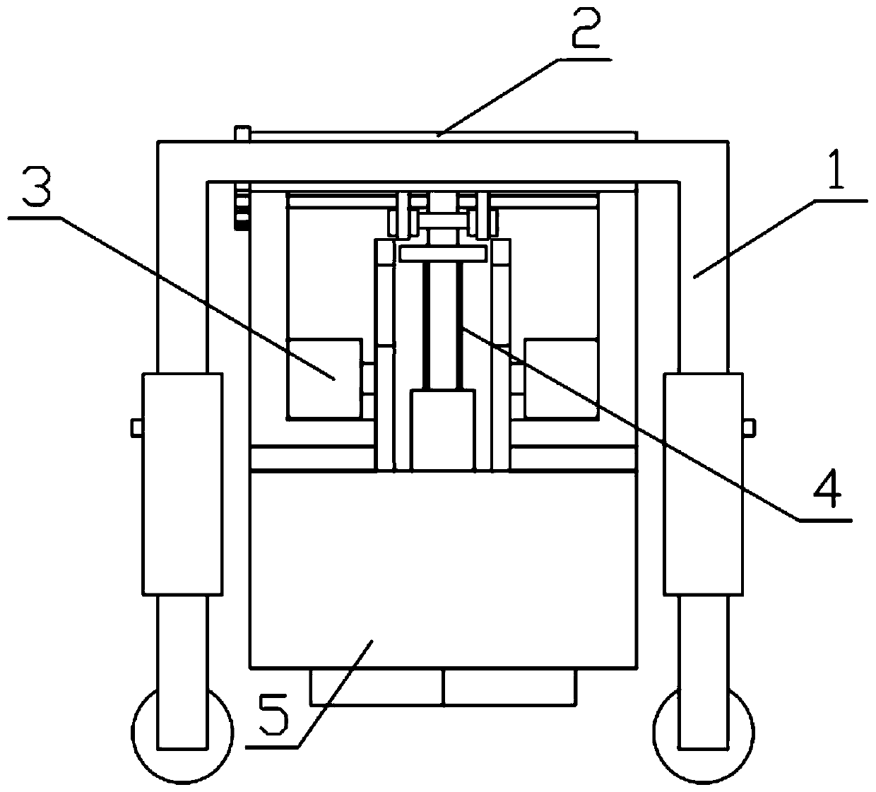
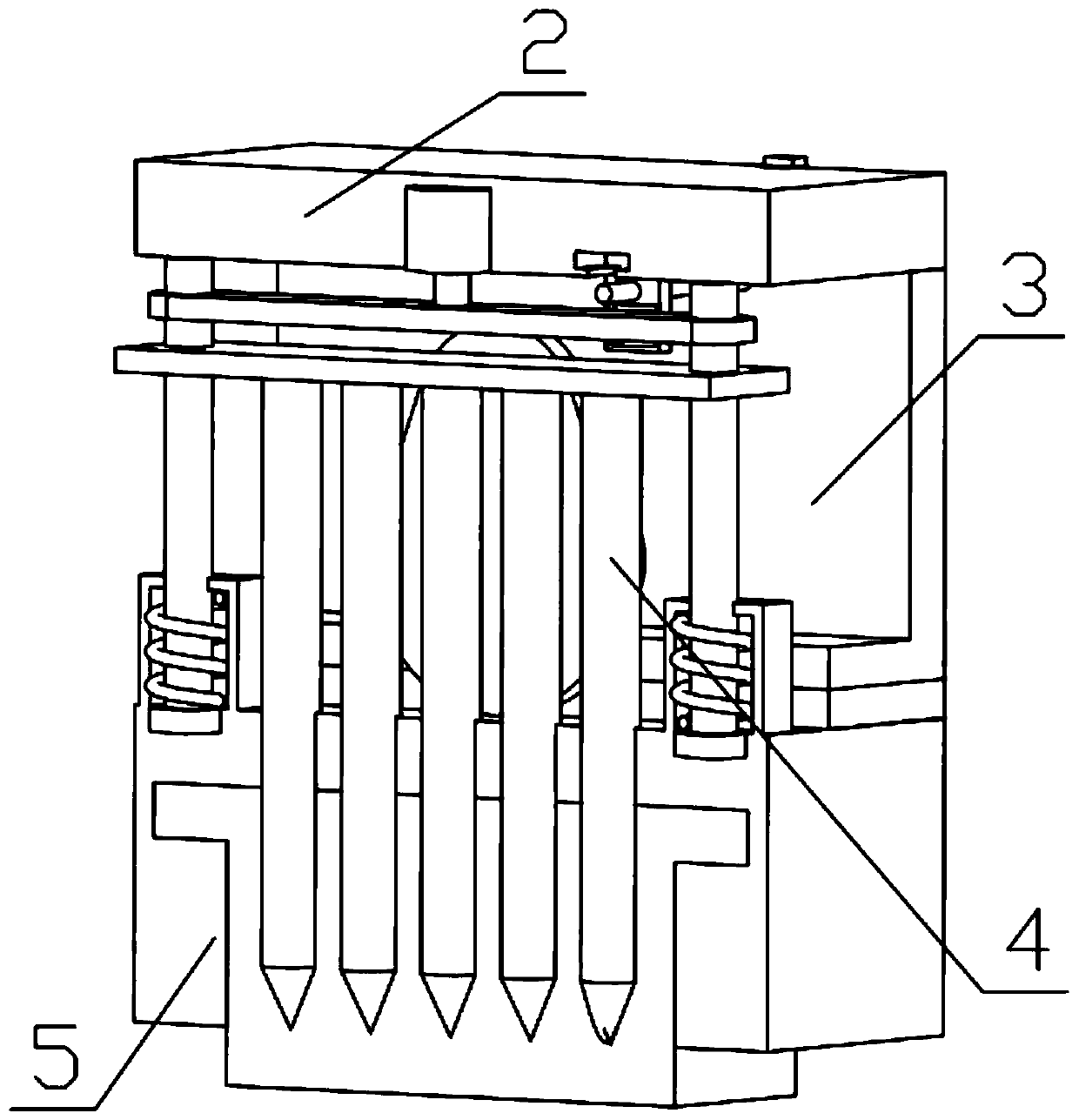
[0042] Combine below Figure 1-18 Description of this embodiment, a sandy soil layer compaction device, including a moving mechanism 1, a top plate mechanism 2, a side plate mechanism 3, a soil insertion component 4 and a bottom mechanism 5, is characterized in that: the number of the moving mechanism 1 is Two, respectively fixed on both sides of the top plate mechanism 2, there are two side plate mechanisms 3, respectively fixed on the other two sides of the top plate mechanism 2, and the positions of the side plate mechanisms 3 are relatively symmetrical, and the top plate mechanism 2 is installed There is an inserting soil assembly 4, and the inserting soil assembly 4 is movably installed in the groove of the bottom mechanism 5, and the bottom mechanism 5 is connected with the top plate mechanism 2.

specific Embodiment approach 2

[0044] Combine below Figure 1-18 Describe this embodiment, this embodiment will further explain the first embodiment, the moving mechanism 1 includes a U-shaped frame 1-1, a square pipe sleeve 1-2, a threaded column 1-3, a connecting leg 1-4, and a moving wheel 1-5, the U-shaped frame 1-1 is fixedly connected with the square pipe sleeve 1-2, the connecting leg 1-4 is inserted into the groove of the square pipe sleeve 1-2, and the square pipe sleeve 1-2 is provided with three thread grooves, There are three threaded holes on the connecting leg 1-4, the threaded holes of the connecting leg 1-4 correspond to the thread grooves on the square sleeve 1-2, and the square sleeve 1-2 and the connecting leg 1-4 pass through the threaded column 1-3 is fixedly connected, the connecting legs 1-4 are hinged with the moving wheels 1-5, and the height of the device can be adjusted quickly through the square sleeve 1-2, the threaded column 1-3 and the connecting legs 1-4. Convenient.

specific Embodiment approach 3

[0046] Combine below Figure 1-18Describe this embodiment, this embodiment will further explain the first embodiment, the roof mechanism 2 includes a top plate 2-1, a clip 2-2, a connecting column 2-3, a connecting chain 2-4, and a geared motor 2 -5. Extrusion assembly 2-6, there are two connecting columns 2-3, the connecting columns 2-3 are rotatably installed in the groove of the top plate 2-1, and the geared motor 2-5 is fixed on the top plate On the circular groove of 2-1, two extruding components 2-6 are movably installed in the groove of the top layer board 2-1, and the clip 2-2 is movably installed in the groove of the top layer board 2-1, and the connecting chain 2-4 is meshed with the output end of the geared motor 2-5, and the two extrusion components 2-6 are located on both sides of the connecting chain 2-4; the connecting column 2-3 includes a threaded cylinder 2-3-1, an annular Gear 2-3-2, the ring gear 2-3-2 is fixed on the threaded cylinder 2-3-1, the connectin...


PUM


Abstract

The invention relates to a road related device, in particular to a sand layer compacting device. The sand layer compacting device comprises moving mechanisms, a top plate mechanism, side plate mechanisms, a soil inserting assembly and a bottom layer mechanism. According to the device, when road maintenance or local maintenance of a road is conducted, deep compacting is performed on a base layer, the compaction effect is remarkable, the device is convenient to move, and can be suitable for narrow construction places; the number of the moving mechanisms is two, the moving mechanisms are fixed onthe two sides of the top plate mechanism correspondingly, the number of the side plate mechanisms is two, the side plate mechanisms are fixed to the other two sides of the top plate mechanism correspondingly, the positions of the side plate mechanisms are symmetrical, the soil inserting assembly is installed on the top plate mechanism, the soil inserting assembly is in clearance connection with the bottom layer mechanism through grooves, and the bottom layer mechanism is connected with the top plate mechanism.

Description

technical field [0001] The invention relates to a road-related device, more specifically a sand layer compacting device. Background technique [0002] Road rollers are widely used in road construction, whether it is the compaction of the base layer or the compaction of the road surface, all indispensable, and the existing road rollers are single-wheel or multi-wheel compaction. [0003] This compaction method has many disadvantages: [0004] 1. For the compaction of the road base, based on the gravity of the pressure wheel or the additional force on the upper end, it only acts on the surface of the base; [0005] 2. The volume of the roller is too large to compact small areas; [0006] 3. The road roller is only suitable for wider places and cannot be used in narrow places. Contents of the invention [0007] The main technical problem to be solved by the present invention is to provide a sand layer compaction device. When the device faces road maintenance or partial roa...

Claims


Application Information

Patent Timeline
Patent Type & Authority Applications(China)
IPC IPC(8): E01C19/23E02D3/026
CPCE01C19/23E02D3/026
Inventor 赵世海
Owner 毛照丰
Why Eureka
Try Eureka