A device for compacting sandy soil layers
A compaction device and technology for sandy soil layers, applied in soil protection, roads, buildings, etc., can solve the problems of compaction in small areas, inability to apply in narrow places, and large volume of road rollers. Easy to transport and move
- Summary
- Abstract
- Description
- Claims
- Application Information
AI Technical Summary
Problems solved by technology
Method used
Image
Examples
specific Embodiment approach 1
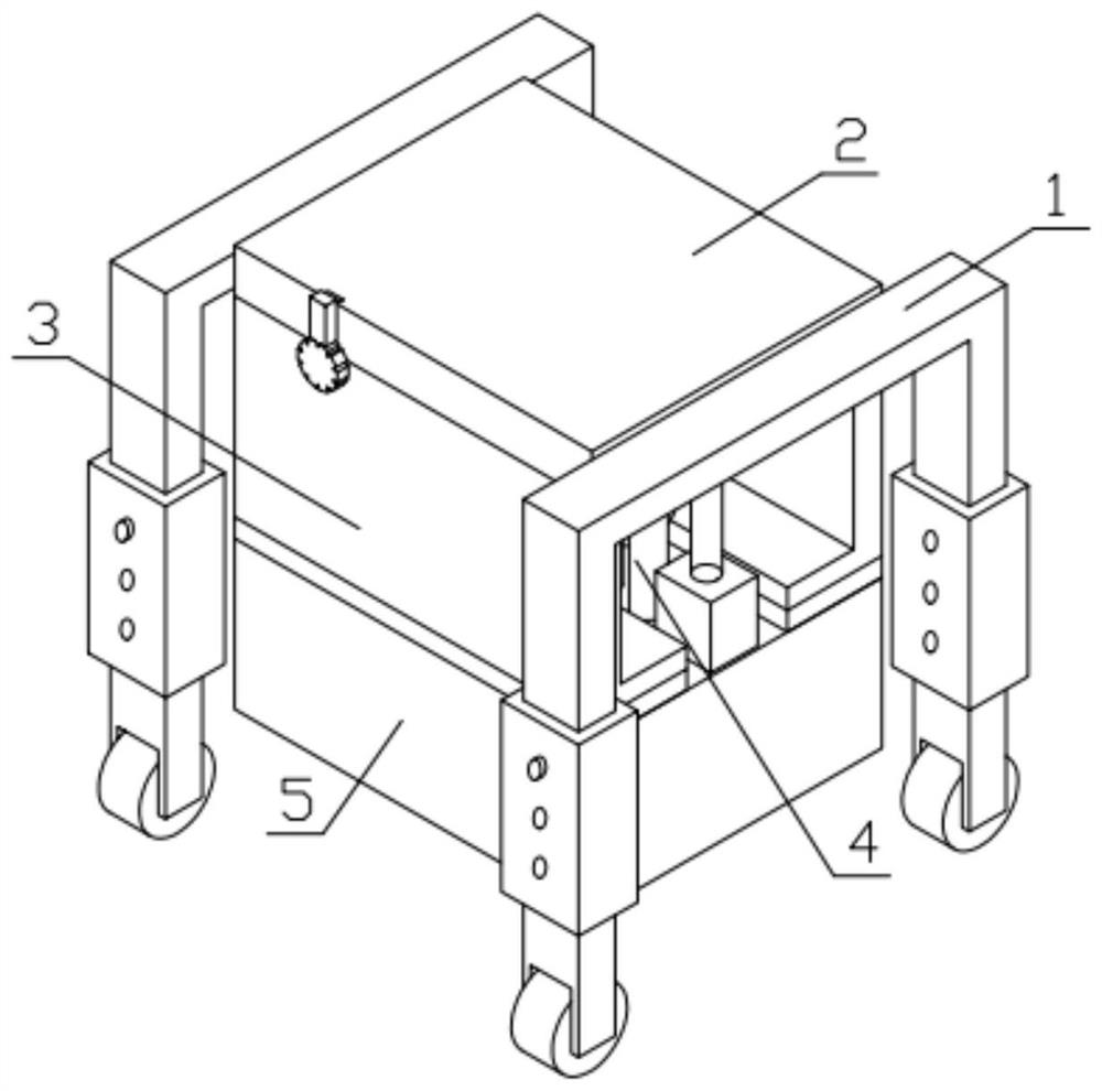
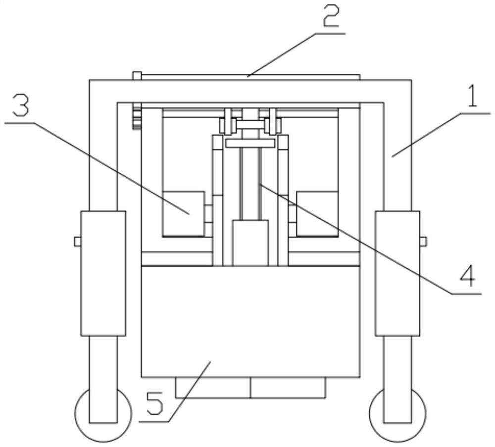
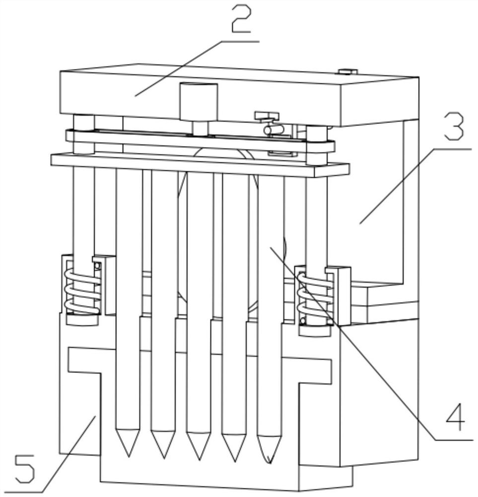
[0042] Combine below Figure 1-18 Description of this embodiment, a sandy soil layer compaction device, including a moving mechanism 1, a top plate mechanism 2, a side plate mechanism 3, a soil insertion component 4 and a bottom mechanism 5, is characterized in that: the number of the moving mechanism 1 is Two, respectively fixed on both sides of the top plate mechanism 2, there are two side plate mechanisms 3, respectively fixed on the other two sides of the top plate mechanism 2, and the positions of the side plate mechanisms 3 are relatively symmetrical, and the top plate mechanism 2 is installed There is an inserting soil assembly 4, and the inserting soil assembly 4 is movably installed in the groove of the bottom mechanism 5, and the bottom mechanism 5 is connected with the top plate mechanism 2.
specific Embodiment approach 2
[0044] Combine below Figure 1-18 Describe this embodiment, this embodiment will further explain the first embodiment, the moving mechanism 1 includes a U-shaped frame 1-1, a square pipe sleeve 1-2, a threaded column 1-3, a connecting leg 1-4, and a moving wheel 1-5, the U-shaped frame 1-1 is fixedly connected with the square pipe sleeve 1-2, the connecting leg 1-4 is inserted into the groove of the square pipe sleeve 1-2, and the square pipe sleeve 1-2 is provided with three thread grooves, There are three threaded holes on the connecting leg 1-4, the threaded holes of the connecting leg 1-4 correspond to the thread grooves on the square sleeve 1-2, and the square sleeve 1-2 and the connecting leg 1-4 pass through the threaded column 1-3 is fixedly connected, the connecting legs 1-4 are hinged with the moving wheels 1-5, and the height of the device can be adjusted quickly through the square sleeve 1-2, the threaded column 1-3 and the connecting legs 1-4. Convenient.
specific Embodiment approach 3
[0046] Combine below Figure 1-18Describe this embodiment, this embodiment will further explain the first embodiment, the roof mechanism 2 includes a top plate 2-1, a clip 2-2, a connecting column 2-3, a connecting chain 2-4, and a geared motor 2 -5. Extrusion assembly 2-6, there are two connecting columns 2-3, the connecting columns 2-3 are rotatably installed in the groove of the top plate 2-1, and the geared motor 2-5 is fixed on the top plate On the circular groove of 2-1, two extruding components 2-6 are movably installed in the groove of the top layer board 2-1, and the clip 2-2 is movably installed in the groove of the top layer board 2-1, and the connecting chain 2-4 is meshed with the output end of the geared motor 2-5, and the two extrusion components 2-6 are located on both sides of the connecting chain 2-4; the connecting column 2-3 includes a threaded cylinder 2-3-1, an annular Gear 2-3-2, the ring gear 2-3-2 is fixed on the threaded cylinder 2-3-1, the connectin...
PUM
 Abstract
Description
Claims
Application Information
 - R&D
- Intellectual Property
- Life Sciences
- Materials
- Tech Scout
- Unparalleled Data Quality
- Higher Quality Content
- 60% Fewer Hallucinations
Browse by: Latest US Patents, China's latest patents, Technical Efficacy Thesaurus, Application Domain, Technology Topic, Popular Technical Reports.
© 2025 PatSnap. All rights reserved.Legal|Privacy policy|Modern Slavery Act Transparency Statement|Sitemap|About US| Contact US: help@patsnap.com


