Construction method of grid beam concrete cast-in-place bridge deck slab of steel box arch bridge
A grid beam and concrete technology, which is applied in bridges, bridge parts, bridge construction, etc., can solve the problems of high bearing capacity of the foundation, broken crossings, etc.
- Summary
- Abstract
- Description
- Claims
- Application Information
AI Technical Summary
Problems solved by technology
Method used
Image

Examples
Embodiment Construction
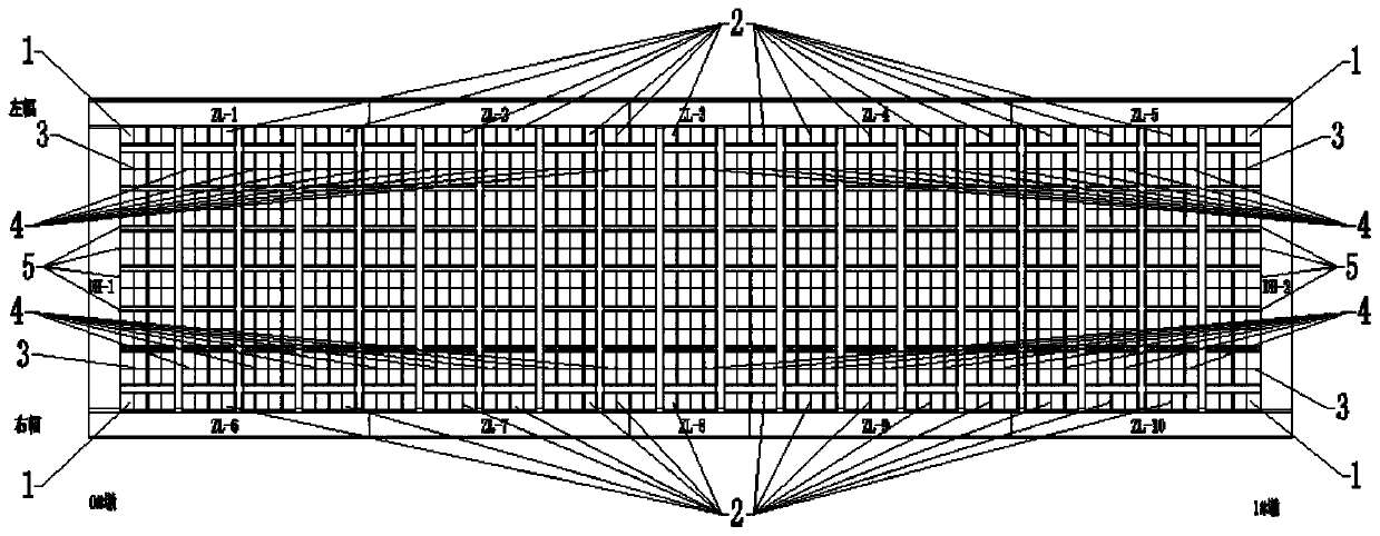
[0048] The specific steps of a construction method for steel box arch bridge grid girder concrete cast-in-place bridge deck include:
[0049] The first step, steel formwork production
[0050] 1.1 According to the specifications and dimensions of the grid beams, draw the "Formwork Production and Installation Drawing".
[0051] 1.2 The steel formwork is completed by purchasing steel plates and cutting them on site. During the production process, the template size and welding quality are strictly controlled.
[0052] 1.3 Intermittent welding is used between the steel formwork stiffener and the steel formwork, the length of the weld is 100mm, the interval is 200mm, and the size of the weld foot is 5mm.
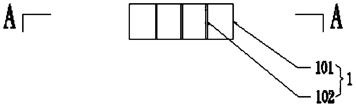
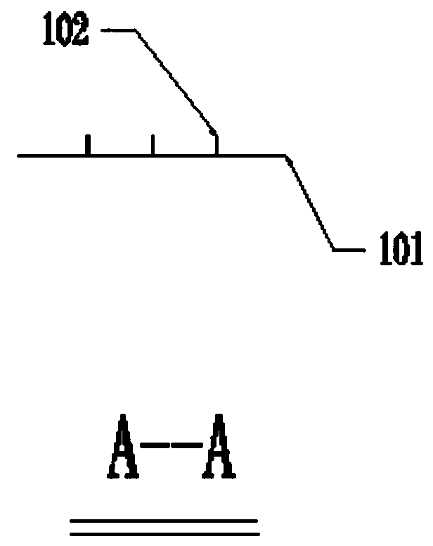
[0053] The second step, steel formwork installation
[0054] 2.1 When installing the steel formwork, the surveyor will set out the line and mark the installation position of the steel formwork. Then use a crane to hoist the steel formwork to the designated position on the gri...
PUM
 Abstract
Description
Claims
Application Information