Fabricated building damping structure

A prefabricated, shock-absorbing mechanism technology, applied in building components, buildings, protective buildings/shelters, etc., can solve the problems of not meeting the needs of modern use, single shock-absorbing mechanism, limited shock-absorbing effect, etc. Strong practicability, good shock absorption effect, ensuring the effect of shock absorption

Inactive Publication Date: 2020-01-10
沛县宝业建筑工业化有限公司
View PDF7 Cites 4 Cited by
  • Summary
  • Abstract
  • Description
  • Claims
  • Application Information

AI Technical Summary

Problems solved by technology

[0003] Chinese patent (Notice No. CN 108824665 A) discloses a shock absorbing mechanism for prefabricated buildings, which arranges a buffer mechanism and a shock absorbing cushion between the base and the support seat, and utilizes the cushion mechanism and the shock absorbing cushion The combined method is used to achieve shock absorption, and the shock absorption effect is good; by setting bellows sleeves on the outside of the base and the

Method used


Image

  • Fabricated building damping structure
  • Fabricated building damping structure
  • Fabricated building damping structure

Examples


Embodiment 1

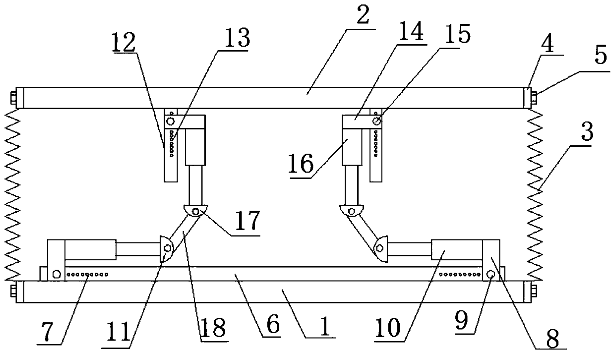
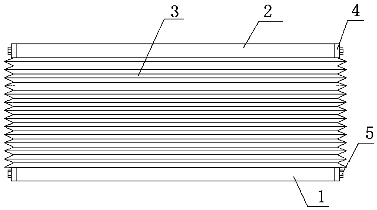
[0023] see Figure 1-3 , in an embodiment of the present invention, a prefabricated building shock absorbing structure includes a base 1, a support base 2 and a protective cover 3, the support base 2 is arranged above the base 1, and the upper and lower ends of the protective cover 3 are respectively Connected with the base 1 and the support base 2, the upper and lower ends of the protective cover 3 are provided with mounting bases 4, the mounting base 4 is connected with the base 1 and the support base 2 through mounting bolts 5, the upper part of the base 1 A first adjusting rod 6 is arranged on the side, and a plurality of first adjusting holes 7 are provided symmetrically on the first adjusting rod 6, and a first adjusting plate 8 is arranged symmetrically on the first adjusting rod 7. The adjustment plate 8 is connected with the first adjustment rod 6 through the cooperation of the first adjustment bolt 9 and the first adjustment hole 7, and the first adjustment plate 8 i...

Embodiment 2

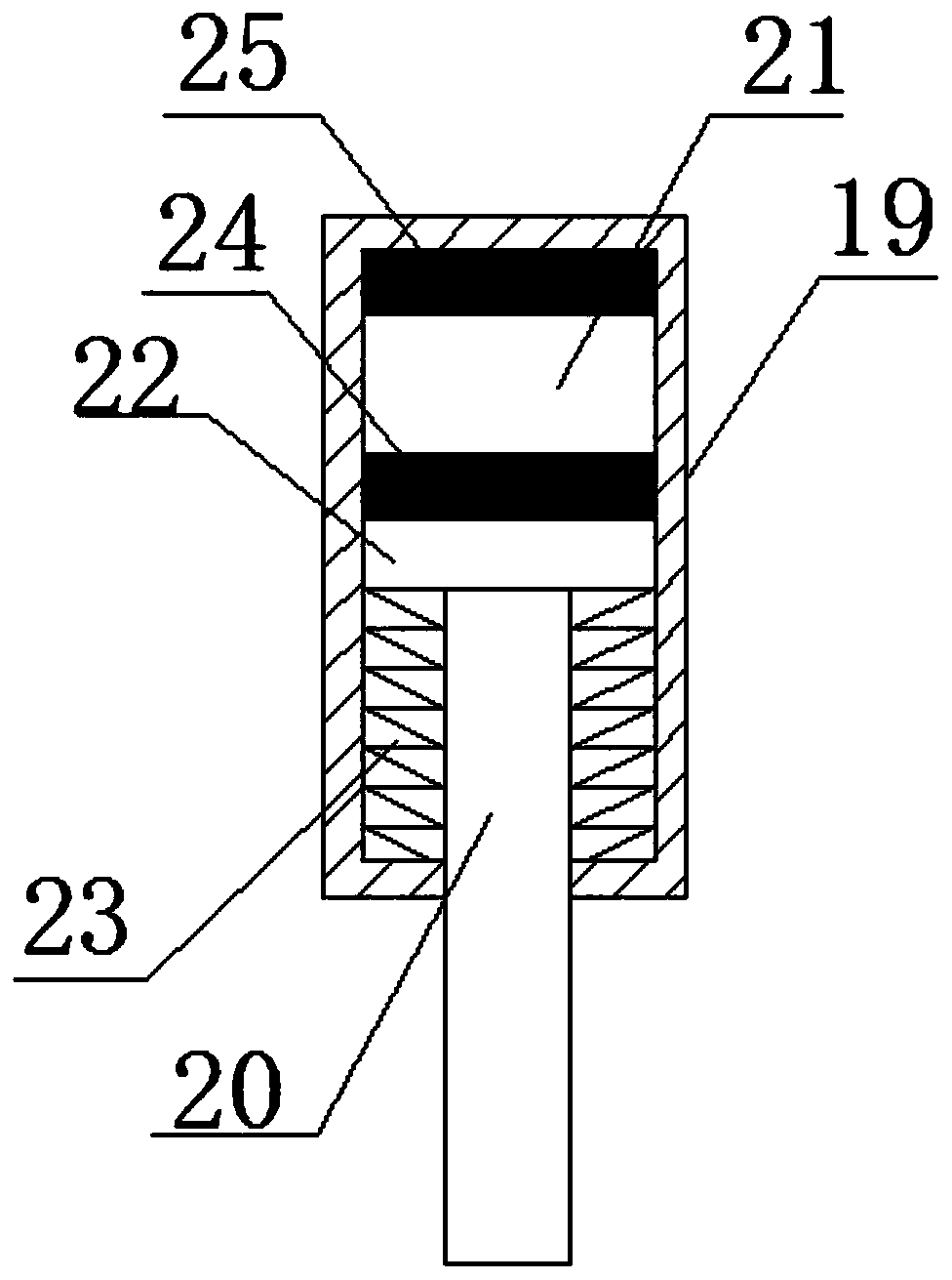
[0027] Both the first shock absorbing mechanism 10 and the second shock absorbing mechanism 16 include a support column 19 and a telescopic column 20, the inside of the support column 20 is provided with a shock absorber chamber 21, and the inside of the shock absorber chamber 21 is provided with a shock absorber. Shock plate 22, the telescopic column 19 stretches into the shock absorbing cavity 21 and is connected with the shock absorbing plate 22, and the lower side of the shock absorbing plate 22 is provided with some shock absorbing springs 23, and the other end of the shock absorbing spring 23 is connected with the shock absorbing plate 22. Cavity 21 is connected, and the upper side of damping plate 22 is provided with lower magnet plate 24, and the inner upper end of shock absorbing cavity 21 is provided with upper magnet plate 25, and the magnetic poles of the opposite surface of described lower magnet plate 24 and upper magnet plate 25 are identical. The arrangement of ...


PUM


Abstract

The invention relates to the field of fabricated buildings, in particular to a fabricated building damping structure. The fabricated building damping structure comprises a base, a support seat and a protective cover. A first adjusting rod is arranged on the upper side of the base. A plurality of first adjusting holes are symmetrically formed in the left side and the right side of the first adjusting rod. First adjusting plates are symmetrically arranged on the left side and the right side of the first adjusting rod. The first adjusting plates are connected with the first adjusting rod throughthe cooperation of first adjusting bolts and the first adjusting holes. A first damping mechanism is arranged on the inner side of each first adjusting plate. Second adjusting rods are symmetrically arranged on the left side and the right side of the lower side of the support seat. A plurality of second adjusting holes are formed in the second adjusting rods. Second adjusting plates are mounted onthe second adjusting rods. The second adjusting plates are connected with the second adjusting rods through the cooperation of second adjusting bolts and the second adjusting holes. Second damping mechanisms are arranged on the lower sides of the second adjusting plates. The fabricated building damping structure is good in damping effect, capable of meeting different use requirements and high inpracticability.

Description

technical field [0001] The invention relates to the field of prefabricated buildings, in particular to a shock-absorbing structure of a prefabricated building. Background technique [0002] Prefabricated buildings refer to buildings assembled on site with prefabricated components. The advantages of this kind of buildings are that they are fast in construction, less restricted by climatic conditions, save labor and improve the quality of buildings. Users can design and build their own houses. The wall body is detachable repeatedly and can be reused, and no construction waste will be generated due to the demolition of the wall. The components used include exterior wall panels, interior wall panels, laminated panels, prefabricated beams, prefabricated columns, stair slabs, etc. The construction is completed through a large number of on-site assembly operations, which greatly reduces the time and manpower compared with the original cast-in-place operation , in line with the req...

Claims


Application Information

Patent Timeline
IPC IPC(8): E04B1/98E04H9/02
CPCE04B1/98E04H9/021
Inventor 李昌伟柯俊羽
Owner 沛县宝业建筑工业化有限公司
Why Eureka
Try Eureka