
Floating type draught fan foundation

A wind turbine foundation, floating technology, applied in the installation/supporting configuration of wind turbines, wind power generation, floating buildings, etc., can solve the problems of not being suitable for use in sea areas below 50 meters, and achieve strong adaptability to water depth and reduce use Cost, the effect of reducing the amount of steel used

Pending Publication Date: 2020-01-10
SHANGHAI ELECTRIC WIND POWER GRP CO LTD
View PDF2 Cites 6 Cited by
  • Summary
  • Abstract
  • Description
  • Claims
  • Application Information

AI Technical Summary

Problems solved by technology

[0006] The technical problem to be solved by the present invention is to overcome the defect that the offshore floating wind turbine foundation in the prior art is not suitable for use in sea areas below 50 meters, and to provide a wind turbine that can not only be used in deep water sea areas, but also transition between 30-50 meters. It is used in deep waters and has a good stability of the floating wind turbine foundation

Method used


Image

  • Floating type draught fan foundation
  • Floating type draught fan foundation
  • Floating type draught fan foundation

Examples


specific Embodiment approach

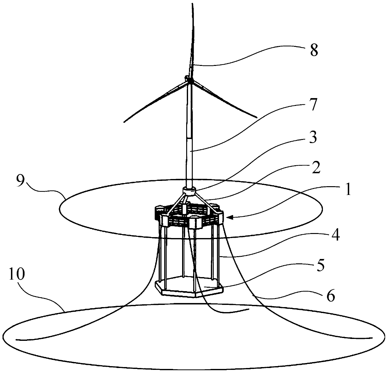
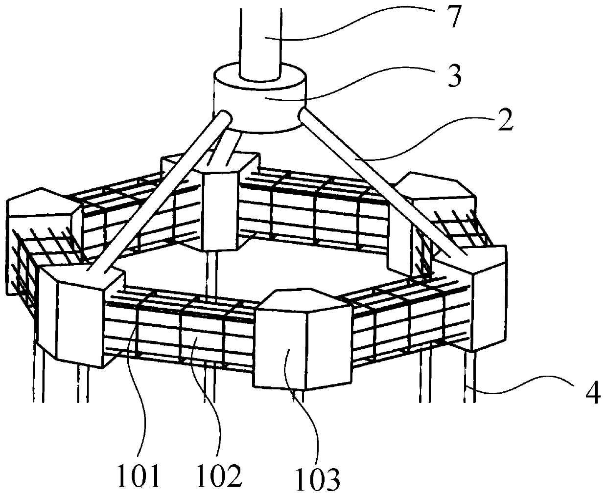
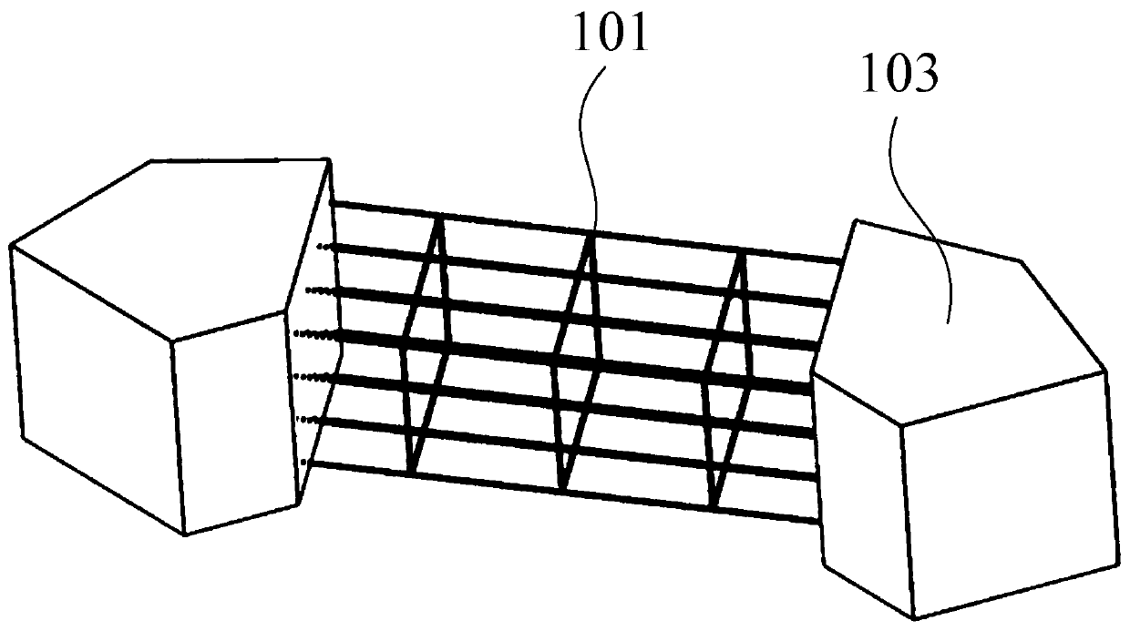
[0059] The overall structure of the floating wind turbine foundation includes tower installation platform 3, connecting body 103, rigid cage 101, floating block 102, rigid connector 4, ballast tank 5, anchor chain 6 and other structures, and wind turbine 8 and tower 7 together form an offshore floating wind turbine system, such as figure 1 shown. The specific implementation is as follows:

[0060] The upper section of the floating fan base transition structure tower installation platform 3 is a steel cylindrical structure with a diameter larger than the outer diameter of the tower 7, and is connected to the section of the tower 7 through a flange. The lower section of the transition structure is a steel cylindrical brace (rigid member 2), and the bottom end of the brace can be fixed to the structural connector 103 by means of anchor bolts, welding, etc.

[0061] The structural connecting body 103 of the floating fan foundation is a steel column, its upper part is fixedly con...


PUM


Abstract

The invention discloses a floating type draught fan foundation. The floating type draught fan foundation comprises a ring-shaped floating structure, a ballast tank and a tower installation platform. The ring-shaped floating structure comprises rigid net boxes and floating blocks, the ring-shaped floating structure is formed by sequentially fixedly connecting the multiple rigid net boxes from end to end, and the rigid net boxes are filled with the floating blocks. The ballast tank is arranged below the ring-shaped floating structure and is connected with the ring-shaped floating structure. Thetower installation platform is arranged on the upper side of the ring-shaped floating structure. The floating blocks are made of a material with the density smaller than that of water, or the floatingblocks are of hollow sealing structures. The floating type draught fan foundation is high in water depth adaptability and good in stability, can be used in a deepwater sea area and can also be used in a sea area with the transition water depth being 30 m to 50 m, due to the structure of filling the net boxes with the floating blocks, the steel use amount can be greatly reduced, and the use cost is reduced.

Description

technical field [0001] The invention relates to the field of offshore wind power generation, in particular to a floating wind turbine foundation. Background technique [0002] In recent years, with the development of wind resources from the near sea to the far sea, a variety of foundation forms of offshore floating wind turbines have emerged. At present, representative floating wind turbine foundation schemes include semi-submersible (Semi-submersible), tension leg type (TLP) and column type (SPAR). Among them, the semi-submersible foundation scheme usually consists of multiple large buoy components connected by diagonal bracing structures. The wind turbine is connected and installed on any buoy through the tower, and the stability of the whole machine is ensured by using the large water surface area and drainage volume of the buoy. The tension leg foundation is a vertically moored floating foundation structure, usually composed of suspended buoys and truss support structu...

Claims


Application Information

Patent Timeline
IPC IPC(8): F03D13/25B63B35/44
CPCB63B35/44B63B2035/446F03D13/22F03D13/25F05B2240/93F05B2240/95Y02E10/72Y02E10/727
Inventor 李华祥张友林王坤鹏蒋勇
Owner SHANGHAI ELECTRIC WIND POWER GRP CO LTD
Learn More