Supercharge Your Innovation With Domain-Expert AI Agents!

Magnetic vortex pump

A swirl pump and magnetic technology, applied in the field of magnetic swirl pumps, can solve the problems of large pump body, complex structure, and easy cavitation, etc., and achieve the effects of less heat, less wear and longer life

Inactive Publication Date: 2020-01-10
安徽龙泉泵阀制造有限公司
View PDF4 Cites 1 Cited by
  • Summary
  • Abstract
  • Description
  • Claims
  • Application Information

AI Technical Summary

Problems solved by technology

In the first method, the impeller can only be enlarged to a certain size. After the impeller outlet diffuses seriously and cavitation is prone to occur, the diameter cannot be increased, and the pump body becomes correspondingly large.
The second method is to increase the impeller, but the structure is very complicated if it is increased to more than 3 stages. If it is a plastic-lined magnetic pump, it is necessary to consider the plastic lining and mechanically lock the impeller axially, and the structure is even more complicated.

Method used


Image

  • Magnetic vortex pump
  • Magnetic vortex pump
  • Magnetic vortex pump

Examples


Embodiment Construction

[0024] The following will clearly and completely describe the technical solutions in the embodiments of the present invention with reference to the accompanying drawings in the embodiments of the present invention. Obviously, the described embodiments are only some, not all, embodiments of the present invention. Based on the embodiments of the present invention, all other embodiments obtained by persons of ordinary skill in the art without making creative efforts belong to the protection scope of the present invention.

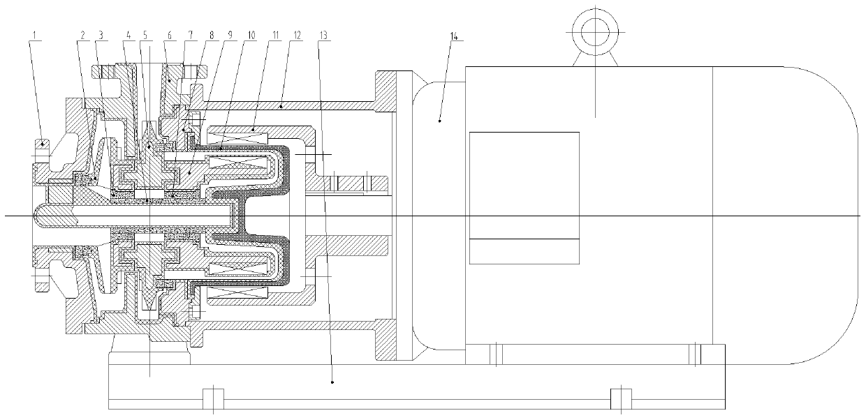
[0025] Such as figure 1 , a magnetic swirl pump, including front cover 1, impeller 2, impeller bearing 3, bushing 4, pressurized impeller 5, pump body 6, rotor bearing 7, pump cover 8, rotor 9, spacer sleeve 10, outer magnetic 11, support 12, base plate 13, motor 14 components constitute.

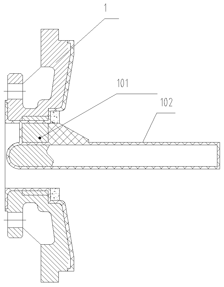
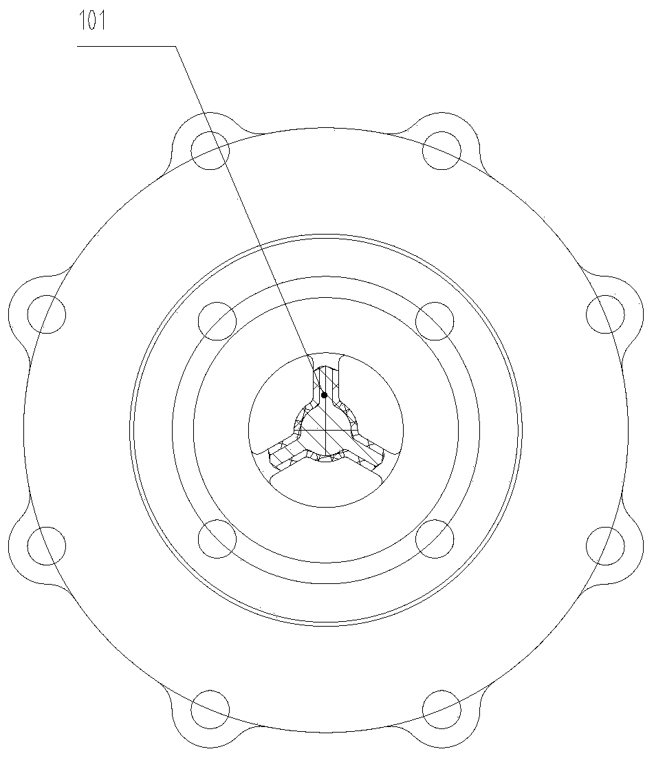
[0026] The front cover 1 is positioned and fixed on the pump body 6 through a metal position. Such as Figure 2-3 , the front cover 1 has a shaft 102 of a triangular sup...


PUM


Abstract

The invention discloses a magnetic vortex pump which comprises a front cover, an impeller, an impeller bearing, a ceramic shaft sleeve, a pressurizing impeller, a pump body, a rotor bearing, a pump cover, a rotor, an isolating bushing and an outer magnetic part. A liquid entering a front pump cavity through the front cover is pressurized for the first time, is then rotatably pressurized by n blades of the pressurizing impeller after flowing into a back pump cavity through a through hole channel and flows out through a diffusion pipe of the pump body. After the rotating speed of the magnetic vortex pump is reduced, the lift is improved to meet an original lift demand at a high speed by increasing the quantity of the blades of the pressurizing impeller while other parts such as the impellerand the pump body are not changed in dimension, so that heat generated by the low rotating speed magnetic vortex pump is small, and the wear is reduced, and therefore, the service life of the pump isprolonged greatly.

Description

technical field [0001] The invention relates to the technical field of pump valves, in particular to a magnetic swirl pump. Background technique [0002] The fixed impeller of the magnetic pump has a fixed head. If the head needs to be increased, there are two methods: 1. Increase the diameter of the impeller; 2. Add one or more impellers. In the first method, the impeller can only be enlarged to a certain size, and the outlet of the impeller diffuses seriously and is prone to cavitation. The diameter cannot be increased any more, and the pump body becomes larger accordingly. The second method is to increase the impeller, but the structure is very complicated if it is increased to more than 3 stages. If it is a plastic-lined magnetic pump, it is necessary to consider the plastic lining and mechanically lock the impeller axially, and the structure is even more complicated. Contents of the invention [0003] Aiming at the deficiencies of the prior art, the present invention...

Claims


Application Information

Patent Timeline
Patent Type & Authority Applications(China)
IPC IPC(8): F04D1/06F04D13/06F04D29/22F04D29/043F04D29/42
CPCF04D1/06F04D13/06F04D29/043F04D29/2261F04D29/2266F04D29/426
Inventor 凤金泉凤元树耿辉吴玲萍凤笑笑
Owner 安徽龙泉泵阀制造有限公司
Features
  • R&D
  • Intellectual Property
  • Life Sciences
  • Materials
  • Tech Scout
  • Unparalleled Data Quality
  • Higher Quality Content
  • 60% Fewer Hallucinations
Learn More