Refrigeration heat exchange pipeline assembly with defrosting function and refrigerant conveying pipe

A technology of heat exchange tubes and pipelines, applied in the field of refrigeration and defrosting, which can solve the problems of not being able to make full use of the heat energy of the defrosting heating wire to quickly defrost, frost on the surface of the pipeline, and affect the vaporization effect, so as to ensure normal and efficient operation, Extend the defrosting cycle and improve the cooling effect

Pending Publication Date: 2020-01-10
刘易铭
View PDF0 Cites 2 Cited by
  • Summary
  • Abstract
  • Description
  • Claims
  • Application Information

AI Technical Summary

Problems solved by technology

These two defrosting methods have their own advantages and disadvantages. The aluminum tube heating wire can be in contact with the end of the fin, but it is far away from the pipeline. The heat at the junction of the fin and the pipeline is relatively low, and the defrosting cycle is longer; the second One is directly heated by radiation, and the heat loss is relatively large
Neither of these two methods can make full use of the heat energy of the defrosting heating wire to quickly defrost
[0005] In addition, in the process of transporting medium in refrigerant pipelines, such as the process of transporting liquid nitrogen, the temperature around the pipeline decreases due to the heat absorption of liquid nitrogen vaporization, resulting in a large amount of frost on the surface of the pipeline, especially when the ambient temperature is low, freezing The phenomenon is more serious and affects the vaporization effect
At this time, the pipeline needs to be defrosted. The most ideal defrosting method is to directly heat the pipeline and fins. The existing method generally uses a hot air fan to defrost locally. Defects such as poor frost effect

Method used


Image

  • Refrigeration heat exchange pipeline assembly with defrosting function and refrigerant conveying pipe
  • Refrigeration heat exchange pipeline assembly with defrosting function and refrigerant conveying pipe
  • Refrigeration heat exchange pipeline assembly with defrosting function and refrigerant conveying pipe

Examples


Embodiment 1

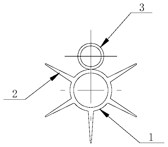
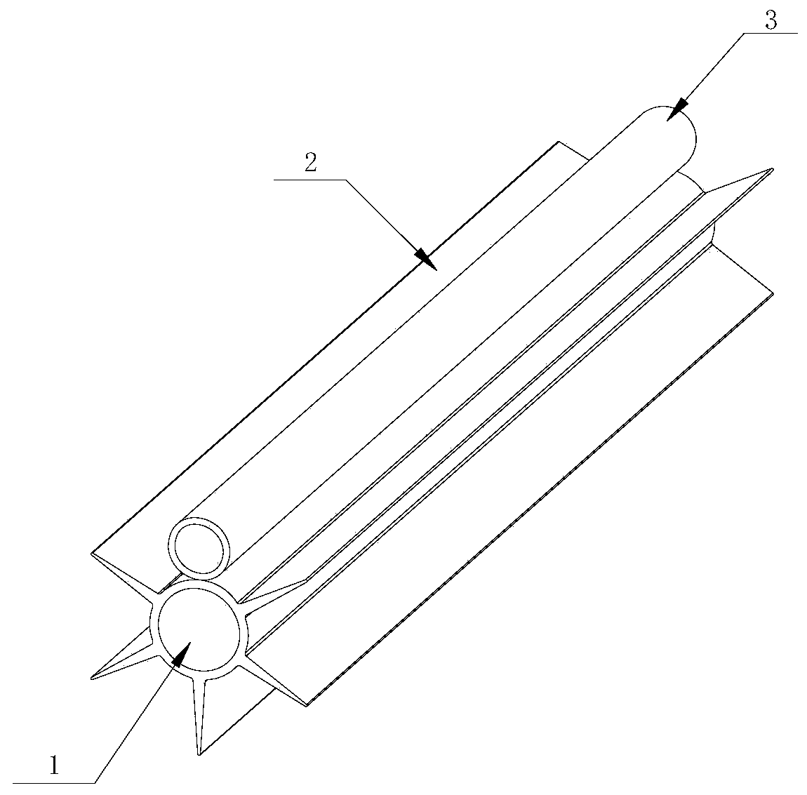
[0044] Example 1, see figure 1 and figure 2 , a refrigeration heat exchange pipeline assembly with defrosting, including a pipeline 1 with an inlet and an outlet, the outer circumference of the pipeline is integrally provided with several continuous heat exchange fins 2, and also includes a pipeline fixed on the pipeline The electric heating tube 3; the length direction of the heat exchange fins is consistent with the axial direction of the pipeline.

[0045] In this embodiment, the heat exchange fins and the pipeline are directly formed by pulling and forming in actual production. Compared with the existing cooling fins installed on the pipeline, the heat dissipation effect of this structure is better than that of the assembled structure, and it is different from the assembled structure. Compared with the omitted fin assembly process; in order to improve the connection strength between the heat exchange fin and the pipeline, the thickness of the root of the fin is greater t...

Embodiment 2

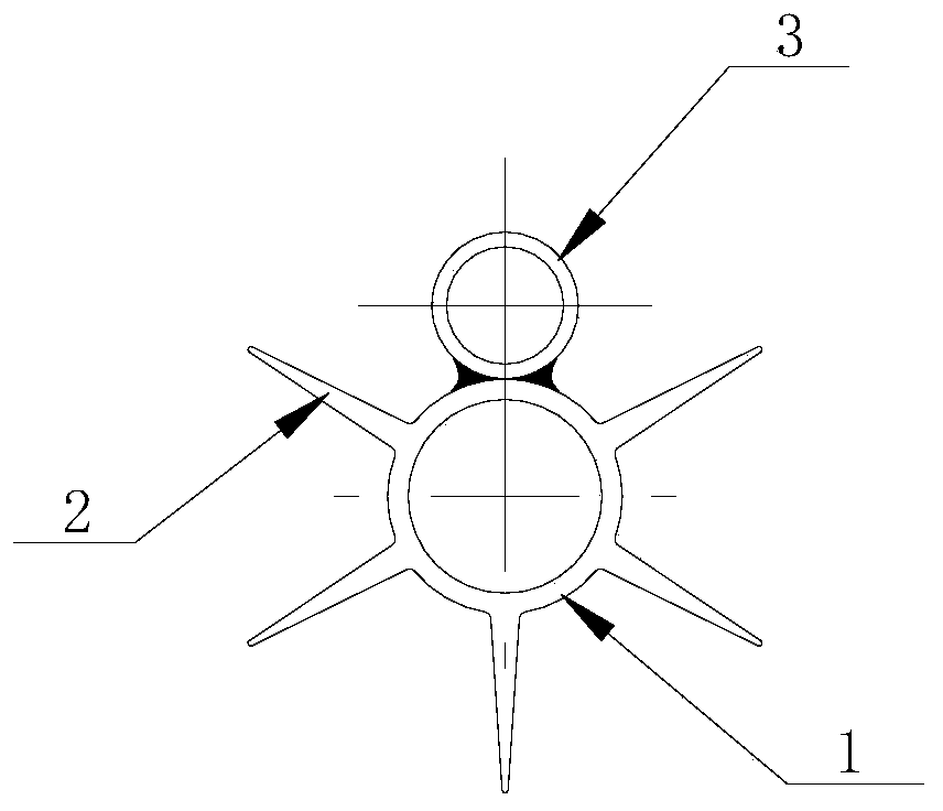
[0046] Example 2, see image 3 , in this embodiment, the electric heating tube is glued between two adjacent heat exchange fins, and is pasted on the outer wall of the pipeline by an adhesive, and the adhesive is made of heat-conducting glue on the market. Bonding, after bonding, the heat transfer will not be affected; the electric heating tube is bonded to the root of the evaporator tube Louis frosting and directly contacts for heat exchange. After the defrosting function is activated, the temperature at this position rises rapidly, reducing its The probability of secondary freezing occurs when the root temperature is low. The fixed method of adhesive is adopted, the installation speed is fast, and it is easy to adjust. It is easy to adjust the position of the electric heating tube in the early stage of curing. Once the electric heating tube is cured, the electric heating tube is relatively stable, and also reduces the production cost.

Embodiment 3

[0047] Example 3, see Figure 4 , the electric heating tube is glued between two adjacent heat exchanging fins, and pasted on the side of the heat exchanging fins by an adhesive.

[0048] The electric heating tube is bonded on the side of the heat exchange fin and the roots that are prone to frost are directly contacted for heat exchange. After the defrosting function is activated, the temperature at this position rises rapidly, and the heat is quickly transferred to the upper part of the pipeline, reducing its cause Probability of secondary icing due to low root and sidewall temperatures. The fixed method of adhesive is adopted, the installation speed is fast, and it is easy to adjust. It is easy to adjust the position of the electric heating tube in the early stage of curing. Once the electric heating tube is cured, the electric heating tube is relatively stable, and also reduces the production cost.


PUM


Abstract

The invention discloses a refrigeration heat exchange pipeline assembly with the defrosting function. The assembly is used for the technical field of refrigeration heat exchange and comprises a pipeline with an inlet and an outlet, multiple continuous heat exchange fins are integrally arranged on the outer circumference of the pipeline, and the assembly further comprises an electric heating pipe fixed to the pipeline. The invention further discloses a refrigerant conveying pipe manufactured through a refrigeration pipeline heat exchange structure. Through the structure, efficient defrosting isachieved, the defrosting period can be greatly prolonged, and the refrigeration effect is improved. The electric heating pipe can remove frost on the fins and the outer wall of the pipeline, the defrosting frequency when an evaporator is used under the low-temperature environment is reduced, normal and efficient running of the evaporator can be ensured, the effective use rate of the refrigerationmedia is higher, the running efficiency of the evaporator is improved, and the assembly is more energy-saving and environment-friendly.

Description

technical field [0001] The invention belongs to the technical field of refrigeration and defrosting, and in particular relates to a refrigeration heat exchange pipeline assembly and a refrigerant delivery pipe with defrosting. Background technique [0002] With the development of refrigeration technology, frost-free refrigerators are becoming more and more popular. At present, the frost-free refrigerators on the market are generally air-cooled refrigerators. The principle of air-cooled refrigerators is to use air for cooling, and high-temperature air flows through the built-in When the evaporator (separated from the inner wall of the refrigerator), due to the high temperature of the air and the low temperature of the evaporator, the two directly exchange heat, the temperature of the air will decrease, and at the same time, the cold air will be blown into the refrigerator; the air-cooled refrigerator is through this The cold air is continuously circulated in the refrigerator ...

Claims


Application Information

Patent Timeline
Patent Type & Authority Applications(China)
IPC IPC(8): F25D21/08F25D23/00F28F1/14F28F1/36F28F19/00
CPCF25D21/08F25D23/006F28F1/14F28F1/36F28F19/006
Inventor 刘易铭
Owner 刘易铭
Why Eureka
Try Eureka