Drying device for plywood production

A technology of drying device and wooden splint, which is applied in the direction of drying, drying machine, drying gas arrangement, etc., can solve the problems of low drying efficiency and inability to meet actual needs well, so as to facilitate drying, avoid omission, Ease of use

Inactive Publication Date: 2020-01-10
湖北天莱木业有限公司
View PDF0 Cites 3 Cited by
  • Summary
  • Abstract
  • Description
  • Claims
  • Application Information

AI Technical Summary

Problems solved by technology

[0003] At present, most of the existing drying devices for wood plywood production on the market have the following deficiencies in the process of use: most of them stack wood blocks together for drying, and the drying efficiency is low. In summary, the existing Most of the drying equipment for plywood production can not meet the actual needs

Method used


Image

  • Drying device for plywood production
  • Drying device for plywood production
  • Drying device for plywood production

Examples


Embodiment 1

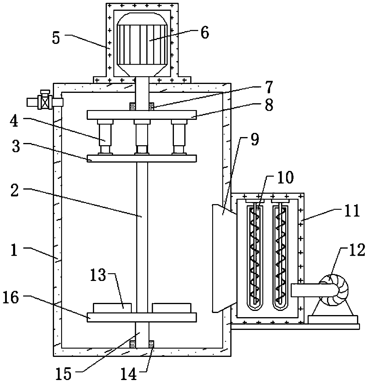
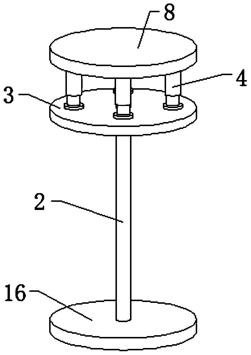
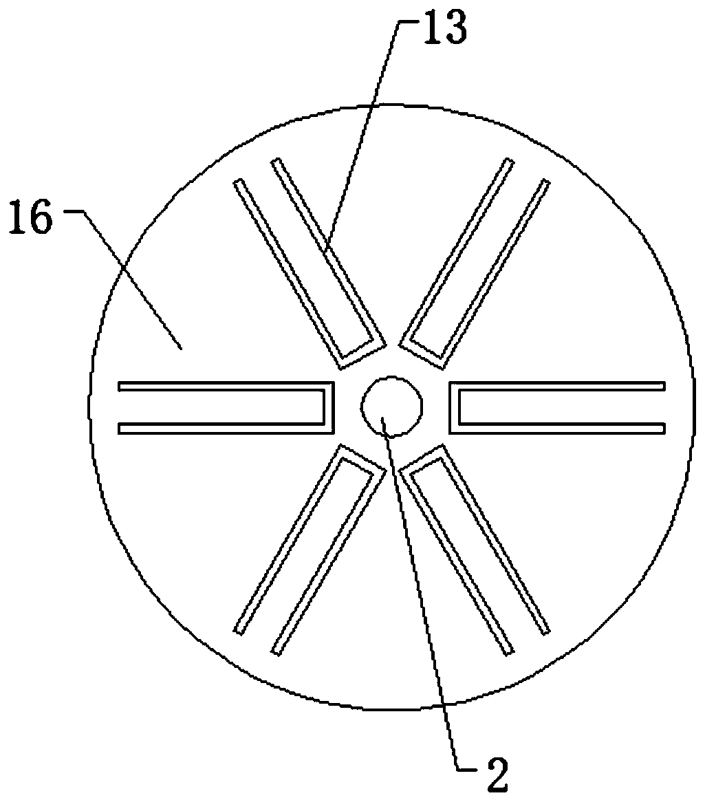
[0023] refer to Figure 1-3 , a drying device for plywood production, comprising a box body 1 and a heating and blowing mechanism, a motor box 5 is fixed to the middle of the outer wall of the top of the box body 1 by bolts, and a motor 6 is fixed to the bottom inner wall of the motor box 5 by bolts, One end of the output shaft of the motor 6 is keyed to a transmission shaft, one end of the transmission shaft is located inside the box body 1, and one end of the transmission shaft is sleeved with a first bearing 7, and the bottom end of the first bearing 7 is welded with a fixed plate 8, and the box body 1 The second bearing 14 is welded at the middle position of the inner wall of the bottom, the connecting shaft 15 is plugged into the inner peripheral wall of the second bearing 14, the top end of the connecting shaft 15 is welded with a supporting plate 16, and the opposite side of the fixing plate 8 and the supporting plate 16 The same support rod 2 is fixed on the outer wall...

Embodiment 2

[0027] refer to Figure 4 , a drying device for wood plywood production. Compared with Embodiment 1, this embodiment also includes four brake universal wheels 17, and the four brake universal wheels 17 are respectively fixed on the bottom outer wall of the box body 1 by bolts. Four corners.

[0028] Working principle: when in use, the bottom of the box body 1 is provided with a brake universal wheel 17, which makes the device move conveniently and facilitates the device to move to a suitable working place.


PUM


Abstract

The invention discloses a drying device for plywood production. The drying device comprises a box body and a heating air-blowing mechanism, wherein the middle position of the top outer wall of the boxbody is fixedly equipped with a motor box through a bolt; a motor is fixedly arranged on the bottom inner wall of the motor box through a bolt; one end of the output shaft of the motor is in key connection with a transmission shaft; one end of the transmission shaft is positioned inside the box body; one end of the transmission shaft is in sleeve connection with a first bearing; the bottom end ofthe first bearing is welded with a fixed plate; the middle position of the bottom inner wall of the box body is welded with a second bearing; a connecting shaft is spliced on the peripheral inner wall of the second bearing; and the top end of the connecting shaft is welded with a supporting plate. According to the drying device for plywood production disclosed by the invention, one end of plywoodwith specified thickness is separately put into a blocking slot plate, an electric telescopic pole is started, the electric telescopic pole drives a pressure plate to move downwards to be in contactwith the top end of the plywood for extruding and fixing the plywood, so that fixation of each wooden board is guaranteed, and wooden boards are not in contact, and therefore, drying work is convenient.

Description

technical field [0001] The invention relates to the technical field of wood plywood production, in particular to a drying device for wood plywood production. Background technique [0002] Wood plywood is a board made directly by compressing wood and cutting together. Wood plywood is firmly pasted, high in flatness, and fine in workmanship. It is often used in furniture decoration and is deeply loved by people. Wood plywood is in the production process. Many steps are required, one of which is that the wooden plywood needs to be dried after it is made, so a drying device is required. [0003] At present, most of the existing drying devices for wood plywood production on the market have the following deficiencies in the process of use: most of them stack wood blocks together for drying, and the drying efficiency is low. In summary, the existing Most of the drying devices for plywood production in China can't meet the actual needs very well. Contents of the invention [000...

Claims


Application Information

Patent Timeline
Patent Type & Authority Applications(China)
IPC IPC(8): F26B11/18F26B21/00
CPCF26B11/18F26B21/001
Inventor 张荣华
Owner 湖北天莱木业有限公司
Why Eureka
Try Eureka