Simulation environment hydraulic pressure stabilizing device suitable for dynamic loading and application method thereof

A technology of simulating environment and dynamic loading, applied in the field of testing, it can solve problems such as poor applicability, large volume, and liquid pressure changes, and achieve the effect of simple assembly and disassembly, flexible application and convenient operation.

Pending Publication Date: 2020-01-10
HOHAI UNIV
View PDF0 Cites 2 Cited by
  • Summary
  • Abstract
  • Description
  • Claims
  • Application Information

AI Technical Summary

Problems solved by technology

However, the existing hydraulic devices are mainly designed for the separate Hopkinson pressure bar test, and all have the following disadvantages: during the loading process, the incident rod will quickly enter the pressure vessel, and the time it takes for the transmission rod to exit the pressure vessel There is a hysteresis, which causes the liquid volume in the pressure vessel to be compressed in a short time, which causes the liquid pressure to change in a short time and cannot provide stable hydraulic pressure
Although some devices adopt the method of enlarging the oil cylinder and increasing the air bag to reduce the water pressure change during the loading process, this can only play a role in passive relief, but cannot fundamentally eliminate pressure fluctuations
And this type of device is bulky, the installation remains unchanged, and the existence of the airbag makes it have a greater safety hazard under high pressure
In addition, most of the currently existing devices are only suitable for separate Hopkinson compression bar loading, not for other loading methods, such as drop weight loading, universal testing machine loading, etc., which have poor applicability

Method used


Image

  • Simulation environment hydraulic pressure stabilizing device suitable for dynamic loading and application method thereof
  • Simulation environment hydraulic pressure stabilizing device suitable for dynamic loading and application method thereof
  • Simulation environment hydraulic pressure stabilizing device suitable for dynamic loading and application method thereof

Examples


Embodiment 1

[0046] A simulated environment hydraulic pressure stabilizing device and application method suitable for dynamic loading, using a universal testing machine as a loading device, comprising the following steps:

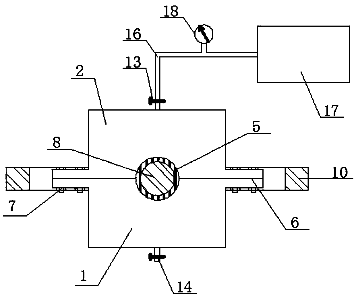
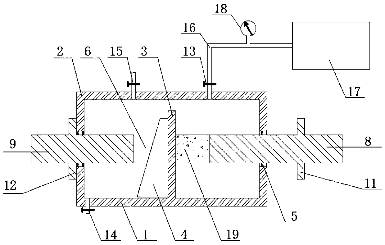
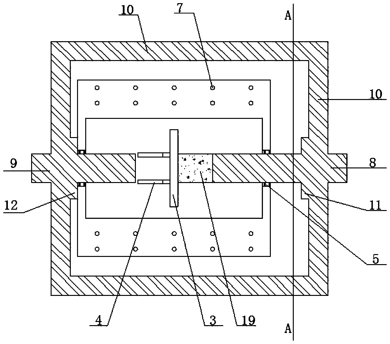
[0047] Step 1, remove the upper cylinder body 2, place the cubic test piece 19 between the loading rod 8 and the bearing surface 3, and use the loading rod 8 to compress the test piece 19;

[0048] Step 2, close the upper cylinder body 2 and the lower cylinder body 1, place a rubber cushion layer 6 on the contact surface between the upper cylinder body 2 and the lower cylinder body 1, and place the upper cylinder body 2, the lower cylinder body 1 and the loading rod 8, A seal 5 is installed at the contact surface of the pressure stabilizing rod 9, and the upper cylinder body 2 and the lower cylinder body 1 are tightened by bolts 7;

[0049]Step 3, place the cylinder vertically so that the loading end of the universal testing machine is in contact with the outer end of t...

Embodiment 2

[0054] A simulated environment hydraulic pressure stabilizing device and application method suitable for dynamic loading, using SHPB as a loading device, comprising the following steps:

[0055] Step 1, remove the upper cylinder body 2, place the cylindrical test piece 19 between the loading rod 8 and the bearing surface 3, and use the loading rod 8 to compress the sample to be tested;

[0056] Step 2, close the upper cylinder body 2 and the lower cylinder body 1, place a rubber cushion layer 6 on the contact surface between the upper cylinder body 2 and the lower cylinder body 1, and place the upper cylinder body 2, the lower cylinder body 1 and the loading rod 8, A seal 5 is installed at the contact surface of the pressure stabilizing rod 9, and the upper cylinder body 2 and the lower cylinder body 1 are tightened by bolts 7;

[0057] Step 3, place the cylinder horizontally so that the end of the incident rod of the SHPB is in contact with the outer end of the loading rod 8 ...


PUM


Abstract

The invention discloses a simulation environment hydraulic pressure stabilizing device suitable for dynamic loading and an application method thereof. The device comprises an upper cylinder body, a lower cylinder body, a loading unit and a pressurization unit, wherein a drain valve is arranged at the bottom of the lower cylinder body, and a bearing surface is arranged inside the lower cylinder body; the upper cylinder body is combined with the lower cylinder body in a covering mode, and reserved holes allowing the loading unit to penetrate through are formed in covering positions; an exhaust valve is arranged at the top of the upper cylinder body; the loading unit comprises a loading bar, a pressure stabilizing bar, a rigid tie bar, a first limiter and a second limiter; the loading bar andthe pressure stabilizing bar are connected to form a rigid whole through the rigid tie bar and extend into the cylinder bodies from the reserved holes in the two sides of the upper cylinder body andthe lower cylinder body respectively; the first limiter and the second limiter are arranged on the loading bar and the pressure stabilizing bar respectively; the pressurization unit comprises a liquidinlet valve, a liquid inlet pipe, a high-pressure injection device and a pressure gauge; the liquid inlet valve is connected with the upper cylinder body; the high-pressure injection device is connected with the liquid inlet valve through the liquid inlet pipe; and the pressure gauge is arranged on the liquid inlet pipe. The technical scheme can provide stable hydraulic pressure for various loading modes.

Description

technical field [0001] The invention belongs to the technical field of testing, and in particular relates to a simulated environment hydraulic pressure stabilizing device suitable for dynamic loading and an application method thereof. Background technique [0002] For underwater structures such as dams, bridge piers, and subsea tunnels, the concrete will continue to be subjected to water pressure while being loaded. Accurate evaluation of the static and dynamic performance of materials under hydraulic pressure in various media is crucial to ensure the safe use of underwater structures. There is a need for an apparatus capable of simulating a stable ambient hydraulic pressure for static and dynamic loading tests. However, the existing hydraulic devices are mainly designed for the separate Hopkinson pressure bar test, and all have the following disadvantages: during the loading process, the incident rod will quickly enter the pressure vessel, and the time it takes for the tra...

Claims


Application Information

Patent Timeline
Patent Type & Authority Applications(China)
IPC IPC(8): G01N3/32G01N3/36G01N3/02
CPCG01N3/02G01N3/32G01N3/36G01N2203/001G01N2203/0019G01N2203/0048G01N2203/0244
Inventor 周继凯金松赵夕瑶田韵邰雅婷柴祯梁远志
Owner HOHAI UNIV
Why Eureka
Try Eureka