Eureka AIR delivers breakthrough ideas for toughest innovation challenges, trusted by R&D personnel around the world.

Radio frequency identification reader and using method thereof

A radio frequency identification and reader technology, used in instruments, electromagnetic radiation induction, induction record carriers, etc., can solve the problems of invisible electromagnetic waves, missing labels, and waste.

Pending Publication Date: 2020-01-10
SHENZHEN IDATA MASCH VISION TECH CO LTD
View PDF5 Cites 0 Cited by
  • Summary
  • Abstract
  • Description
  • Claims
  • Application Information

AI Technical Summary

Problems solved by technology

[0003] However, since the electromagnetic waves used for radio frequency identification are invisible, the reader is blind when reading the tag, and the user does not know where the tag is read.
And because the antenna of the reader uses the same radiation angle to read the tags regardless of the distance of the items to be counted, if the radiation angle is too small when reading close-range items, some tags will be missed and not read, and When reading long-distance items, if the radiation angle is too large, the power consumption will be too high, resulting in waste

Method used


Image

  • Radio frequency identification reader and using method thereof
  • Radio frequency identification reader and using method thereof
  • Radio frequency identification reader and using method thereof

Examples


Embodiment Construction

[0028] In order to facilitate a better understanding of the purpose, structure, features, and effects of the present invention, the present invention will now be further described in conjunction with the accompanying drawings and specific embodiments.

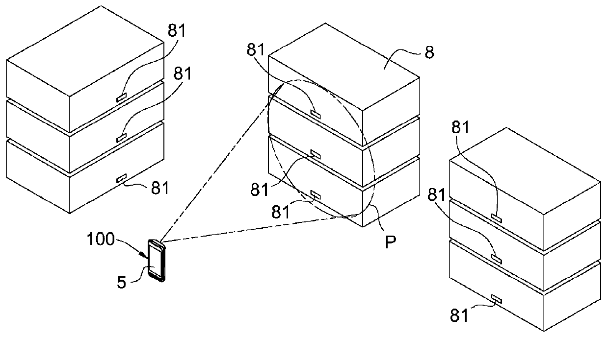
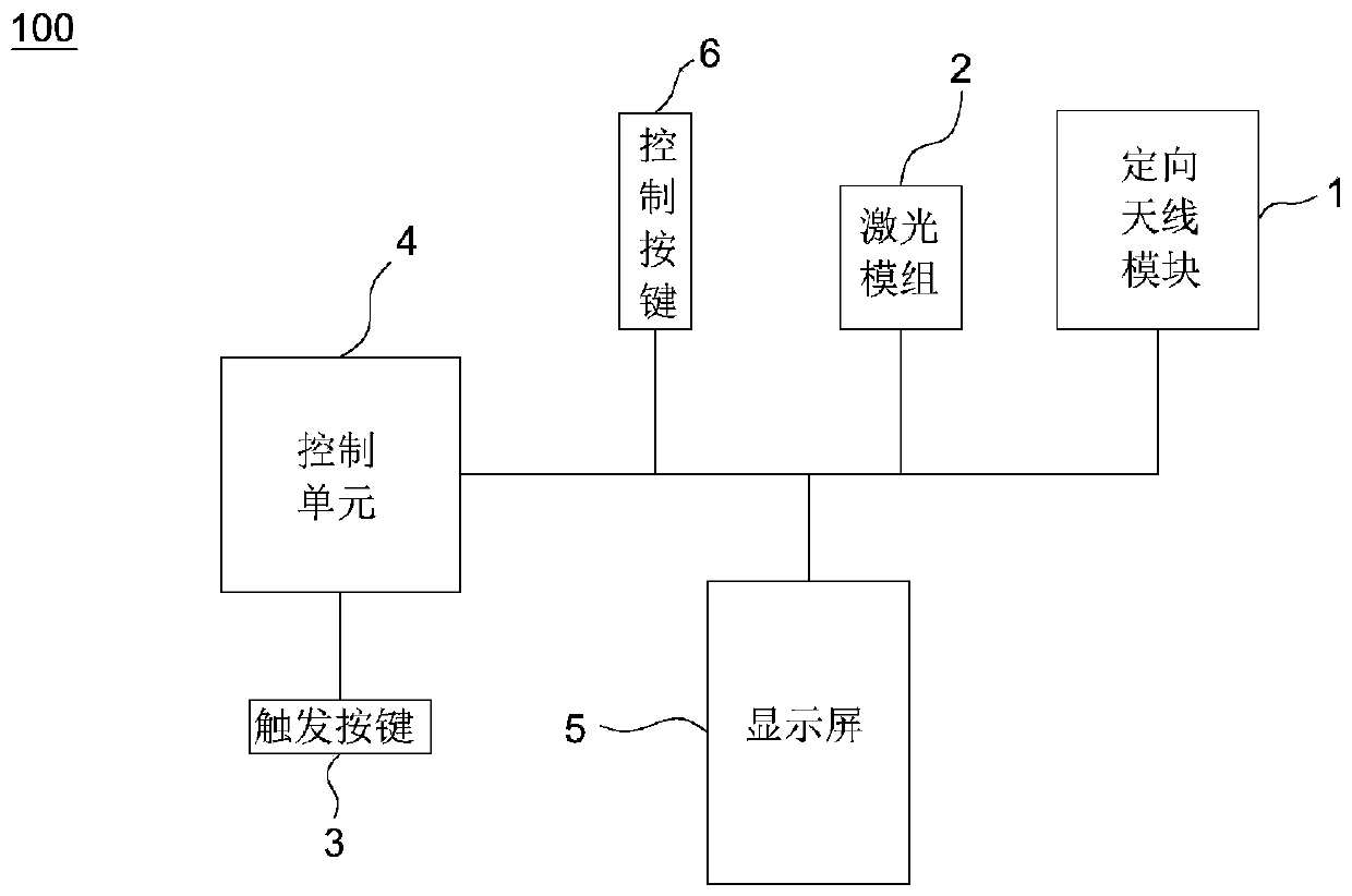
[0029] like figure 1 and figure 2 As shown, the radio frequency identification reader 100 of the present invention mainly includes a directional antenna module 1 , a laser module 2 , a trigger button 3 , a control unit 4 and a display screen 5 .

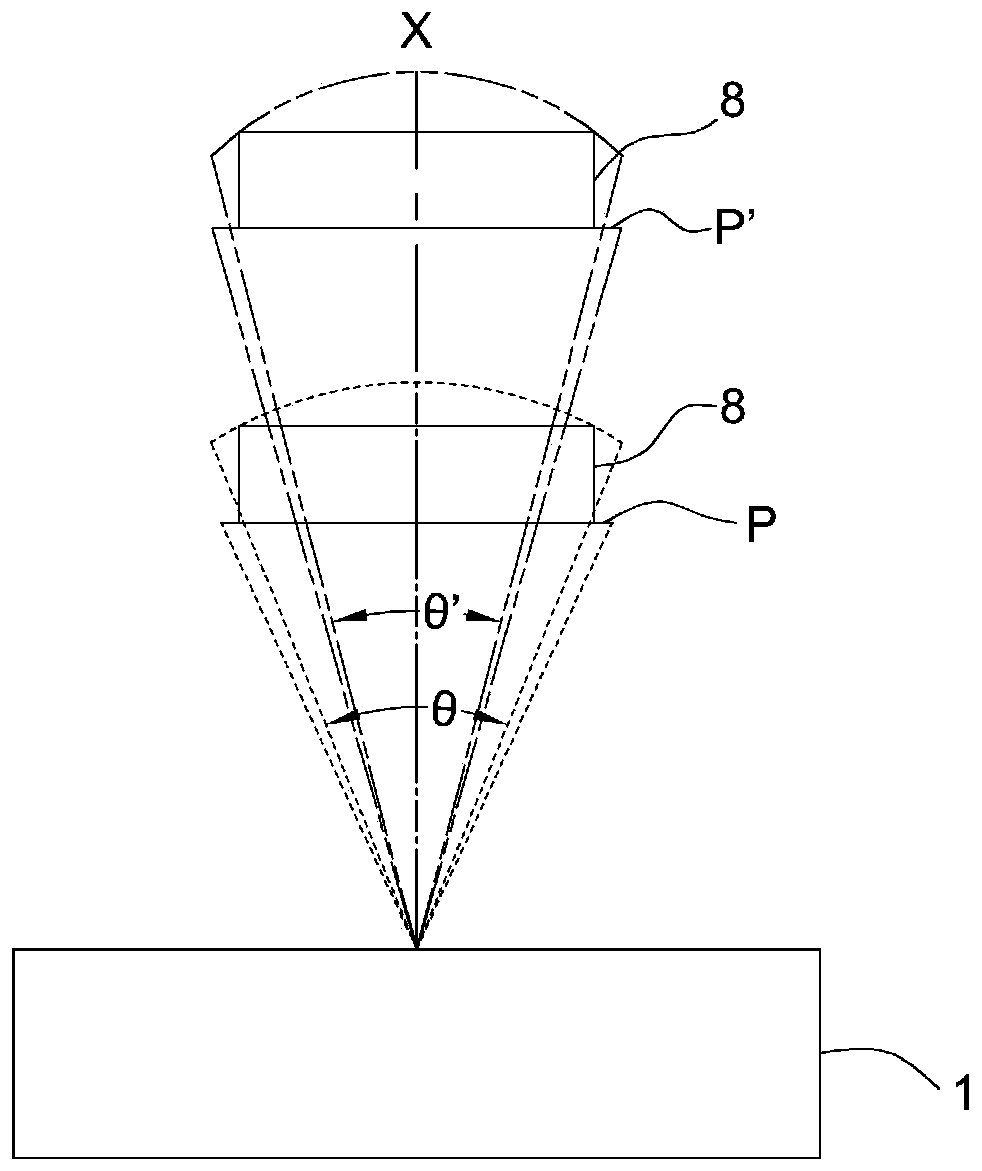
[0030] like image 3 and Figure 4 As shown, the directional antenna module 1 is designed to transmit or receive signals through various radiation angles (referring to horizontal radiation angles) of different sizes, and the vertical direction of the directional antenna module 1 at different distances along the maximum radiation direction X The receiving ranges A and A' on the plane are all known shapes through accurate measurement, and the shape can be adjusted to a regular shape...


PUM


Abstract

The invention provides a radio frequency identification reader, which is characterized by comprising a directional antenna module used for directionally transmitting or receiving signals, a laser module which is used for aiming at a to-be-identified object, and a radio frequency identification reader which has a first working mode and a second working mode, wherein in the first working mode, the directional antenna module transmits or receives signals at a first radiation angle, and the laser module generates a first aiming pattern; in the second working mode, the directional antenna module transmits or receives signals at a second radiation angle, and the laser module generates a second aiming pattern; and the first radiation angle is larger than the second radiation angle, and the firstaiming pattern is used for indicating the range of the first radiation angle, and the second aiming pattern is used for indicating the range of the second radiation angle.

Description

technical field [0001] The invention relates to a radio frequency identification reader and its usage method, in particular to a radio frequency identification reader with adjustable radiation angle and its usage method. Background technique: [0002] Radio frequency identification technology (Radio Frequency Identification, RFID) is a kind of automatic identification technology, which performs non-contact two-way data communication through radio frequency, and uses radio frequency to read and write recording media (electronic tags or radio frequency cards), thereby To achieve the purpose of identifying targets and data exchange. A complete RFID system consists of three parts: Reader, Tag and data management system. Its working principle is that the Reader emits a specific frequency of radio wave energy to drive The circuit sends out the internal data, and at this time, the Reader receives and interprets the data sequentially, and sends them to the data management system fo...

Claims


Application Information

Patent Timeline
Patent Type & Authority Applications(China)
IPC IPC(8): G06K7/10
CPCG06K7/10099G06K7/10316G06K7/10722G06K7/10881
Inventor 王冬生申世安赵伟
Owner SHENZHEN IDATA MASCH VISION TECH CO LTD
Why Eureka
Eureka Blog
Learn More