Eureka AIR delivers breakthrough ideas for toughest innovation challenges, trusted by R&D personnel around the world.

Thyristor fault self-test method, circuit, connector and electrical equipment

A self-testing circuit and self-testing technology, which is applied in the direction of circuit devices, emergency protection circuit devices, electrical components, etc., can solve the problems of trigger signal on or off, uncontrolled thyristor, and thyristor failure, etc., to achieve The effect of leakage protection

Active Publication Date: 2021-12-03
SHENZHEN JINGYANG ELECTRONICS CO LTD
View PDF10 Cites 0 Cited by
  • Summary
  • Abstract
  • Description
  • Claims
  • Application Information

AI Technical Summary

Problems solved by technology

At present, leakage protection can be carried out by thyristor in leakage protection circuit, but short circuit or open circuit between pins of thyristor is easy to occur during use of thyristor. This situation is called thyristor failure, and thyristor will not work. It is controlled and cannot be turned on or off through the trigger signal, so that the leakage protection circuit cannot work normally. However, at present, when the leakage protection is performed to detect the thyristor, it is necessary to use an additional AC signal to provide synchronization information, and an additional High-voltage isolation circuit and rectification circuit will have a large cost in terms of cost and complexity in circuit design

Method used


Image

  • Thyristor fault self-test method, circuit, connector and electrical equipment
  • Thyristor fault self-test method, circuit, connector and electrical equipment
  • Thyristor fault self-test method, circuit, connector and electrical equipment

Examples


Embodiment Construction

[0043] The following will clearly and completely describe the technical solutions in the embodiments of the present invention with reference to the accompanying drawings in the embodiments of the present invention. Obviously, the described embodiments are only part of the embodiments of the present invention, not all of them. Based on the embodiments of the present invention, all other embodiments obtained by persons of ordinary skill in the art without creative efforts fall within the protection scope of the present invention.

[0044] It should be noted that all directional indications (such as up, down, left, right, front, back...) in the embodiments of the present invention are only used to explain the relationship between the components in a certain posture (as shown in the accompanying drawings). Relative positional relationship, movement conditions, etc., if the specific posture changes, the directional indication will also change accordingly.

[0045] In addition, the ...


PUM


Abstract

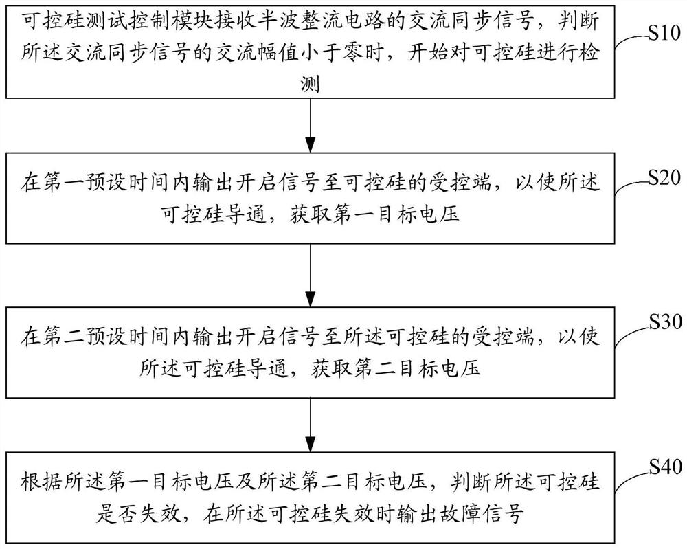
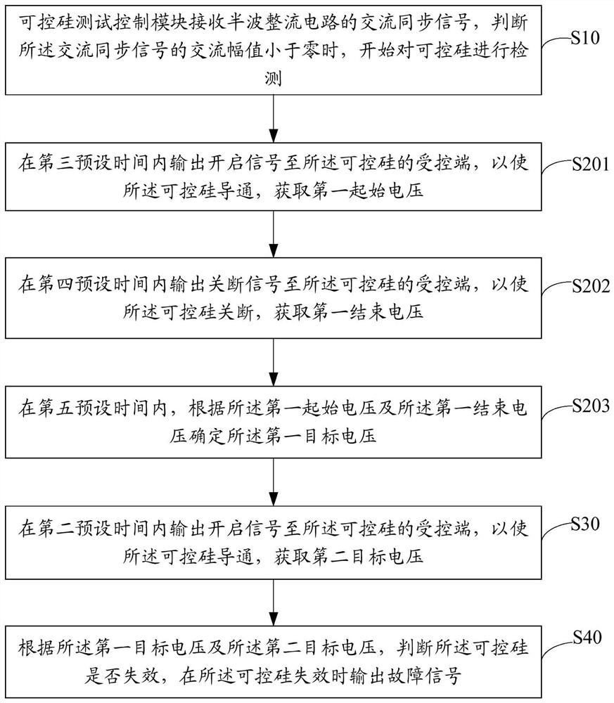
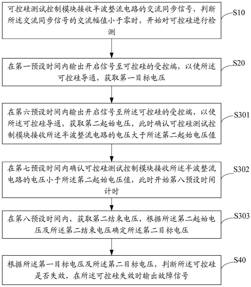
The invention relates to the technical field of leakage detection, and discloses a thyristor fault self-test method, circuit, connector and electrical equipment. The technical scheme of the present invention receives the AC synchronous signal of the half-wave rectification circuit through the thyristor test control module, and starts to detect the thyristor when it is judged that the AC amplitude of the AC synchronous signal is less than zero; within the first preset time outputting a turn-on signal to the controlled end of the thyristor to turn on the thyristor to obtain the first target voltage; outputting the turn-on signal to the controlled end of the thyristor within a second preset time to Turn on the thyristor to obtain a second target voltage; calculate the difference between the first target voltage and the second target voltage and compare it with a threshold to determine whether the thyristor fails, and output when the thyristor fails The fault signal warns the user, and realizes the self-testing of the silicon controlled rectifier in the leakage detection circuit, and does not need human-controlled detection.

Description

technical field [0001] The invention relates to the technical field of electric leakage detection, in particular to a thyristor fault self-test method, circuit, connector and electrical equipment. Background technique [0002] With the rapid popularization of household appliances, the high-frequency components of the load current of modern equipment have increased, and the leakage protection standards have become increasingly stringent. Leakage detection and protection circuits are required to conduct periodic tests to ensure normal operation and avoid possible damage to the human body due to fault conditions. [0003] The new generation of leakage protection standards require that when key circuits or components in the leakage protection circuit fail, the leakage protection chip can detect and start an audible and visual alarm. In this way, serious accidents caused by leakage protection circuit failure can be avoided. At present, leakage protection can be carried out by t...

Claims


Application Information

Patent Timeline
Patent Type & Authority Patents(China)
IPC IPC(8): H02H3/32H02H1/00H02H3/04
CPCH02H1/0007H02H3/044H02H3/32
Inventor 高东兴
Owner SHENZHEN JINGYANG ELECTRONICS CO LTD
Why Eureka
Eureka Blog
Learn More