
Bending forming die for metal plate industry control cabinet

An industrial control and bending forming technology, applied in the field of mechanical processing, can solve the problems of springback, large error, inability to combine extrusion and reciprocating extrusion, etc., and achieve the effect of convenient blanking

Active Publication Date: 2020-01-14
江苏汉达机械有限公司
View PDF6 Cites 2 Cited by
  • Summary
  • Abstract
  • Description
  • Claims
  • Application Information

AI Technical Summary

Problems solved by technology

[0002] There are generally two methods for forming a sheet metal box. The first method is to bend the sheet metal into a box through continuous bending. The second method is to shape the sheet metal at one time by designing a mold. Compared with the first method, the first method: although it is impossible to make the box body through continuous automation, it can only be made with manual assistance and a single piece, but the mold structure is simple, and the mold is formed at one time, with small errors and continuous folding. The way of bending will lead to the accumulation of errors in each bending, which will cause a problem of large errors
[0003] At present, there are the following problems in the mold forming process of sheet metal boxes: 1. The corners of sheet metal bending will rebound without multiple processing; Choose one of the methods for extrusion, and the continuous extrusion and reciprocating extrusion cannot be effectively combined

Method used


Image

  • Bending forming die for metal plate industry control cabinet
  • Bending forming die for metal plate industry control cabinet
  • Bending forming die for metal plate industry control cabinet

Examples


Embodiment Construction

[0026] In order to make the technical means, creative features, goals and effects achieved by the present invention easy to understand, the present invention will be further described below in conjunction with specific illustrations.

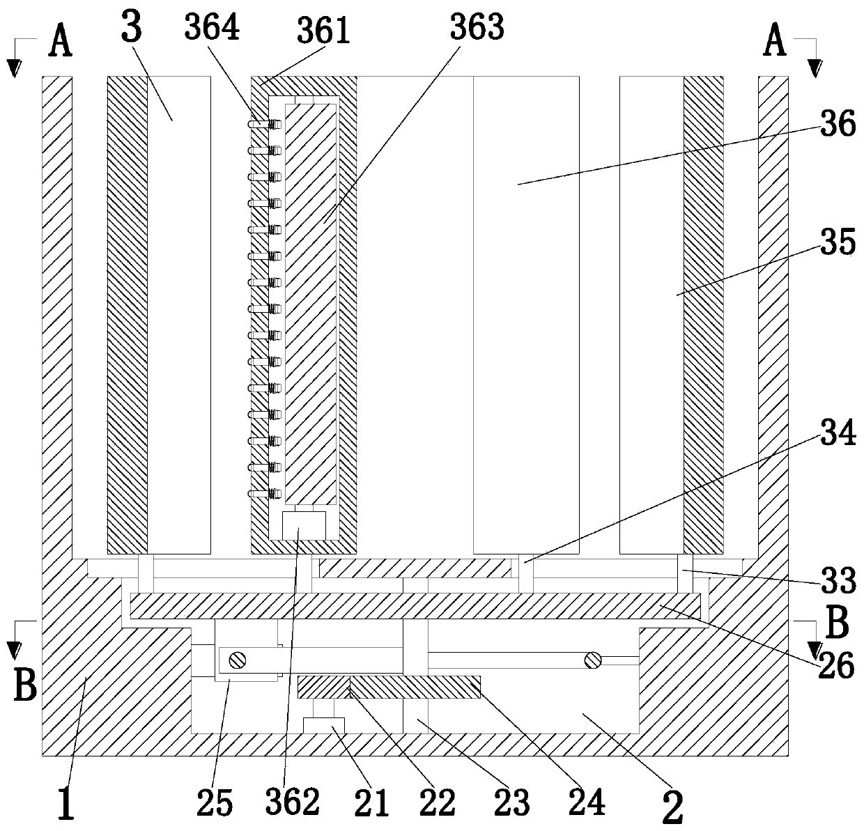
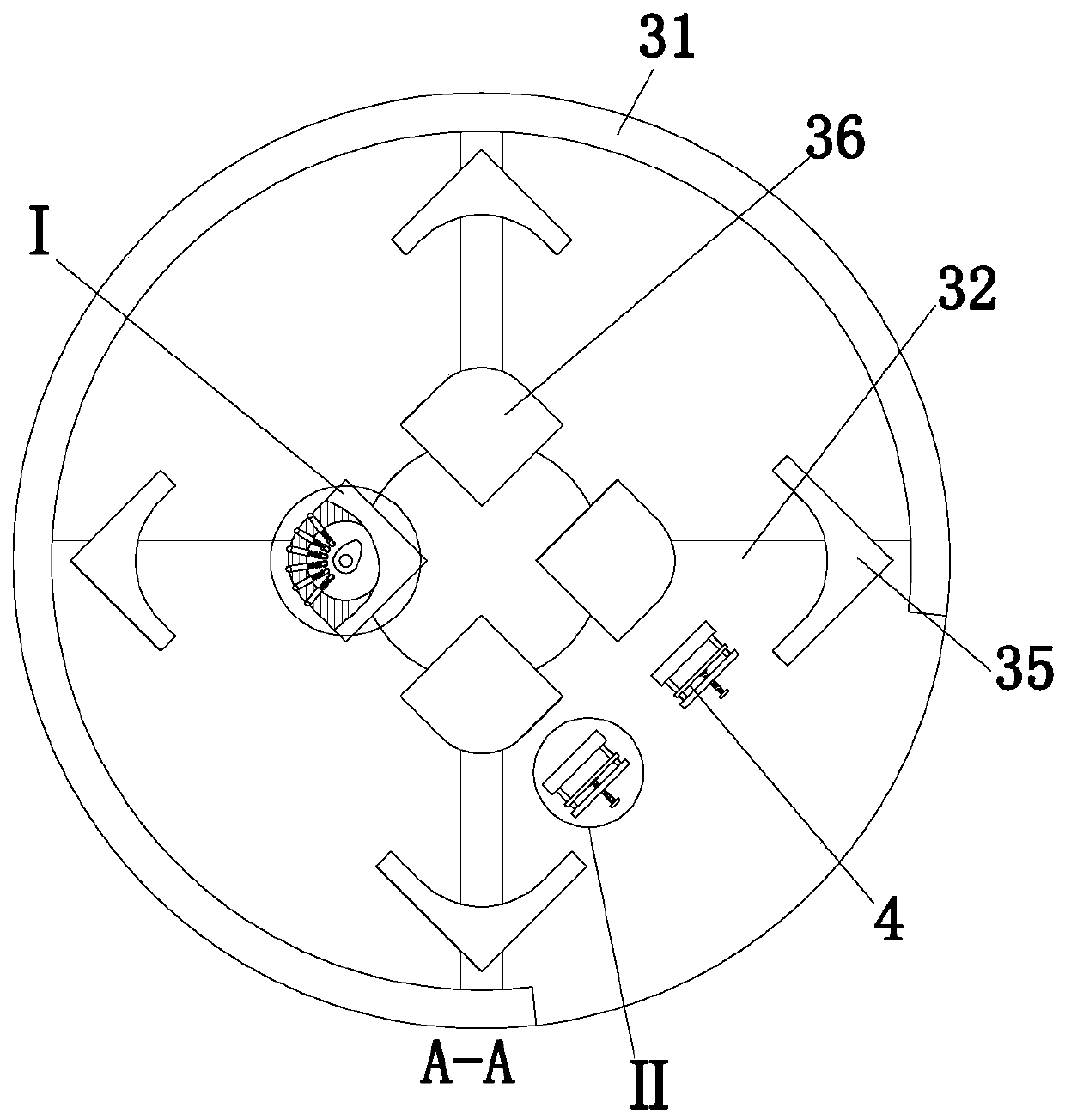
[0027] Such as Figure 1 to Figure 5 As shown, a sheet metal industrial control cabinet bending forming mold includes a base 1, a driving unit 2, a shaping unit 3 and a fixing unit 4. The base 1 is provided with a driving cavity inside, and a driving unit is arranged in the driving cavity 2. A shaping unit 3 is installed on the upper end of the base 1, and a fixing unit 4 is installed on the upper end of the base 1; the fixing unit 4 fixes the plate, and the driving unit 2 drives the shaping unit 3 to simultaneously shape and maintain pressure on the inner and outer sides of the plate.

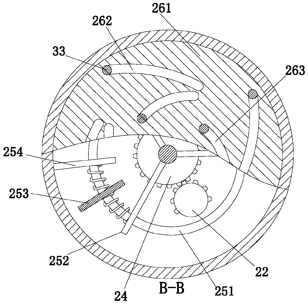
[0028] Described driving unit 2 comprises driving motor 21, half gear 22, rotating shaft 23, driving gear 24, pushing mechanism 25 and groove plate 26, and driv...


PUM


Abstract

The invention relates to a bending forming die for a metal plate industry control cabinet. The die comprises a base, a driving unit, a shaping unit and a fixing unit. A driving cavity is formed in thebase, the driving unit is arranged in the driving cavity, the shaping unit is arranged at the upper end of the base, and the fixing unit is arranged at the upper end of the base. Repeated extrusion and continuous extrusion are effectively combined, so that a rebound phenomenon does not occur at the corner of a metal plate box body, and the inner end and the outer end are simultaneously shaped andpressed; a driving motor is arranged to drive a half gear to be matched with a driving gear, so that the repeated extrusion of the plate by the die is realized, the continuous extrusion is added intothe repeated extrusion process of an inner die and an outer die through springs connected between a push plate, a rotating plate and a fixed plate, and the inner die is designed, so that the plate isrepeatedly hammered by the extrusion mechanism in the continuous extrusion process, and the box body is completely shaped.

Description

technical field [0001] The invention relates to the technical field of mechanical processing, in particular to a bending forming mold for sheet metal industrial control cabinets. Background technique [0002] There are generally two methods for forming a sheet metal box. The first method is to bend the sheet metal into a box through continuous bending. The second method is to shape the sheet metal at one time by designing a mold. Compared with the first method, the first method: although it is impossible to make the box body through continuous automation, it can only be made with manual assistance and a single piece, but the mold structure is simple, and the mold is formed at one time, with small errors and continuous folding. The way of bending will lead to the accumulation of errors in each bending, which will cause a problem of large errors. [0003] At present, there are the following problems in the mold forming process of sheet metal boxes: 1. The corners of sheet met...

Claims


Application Information

Patent Timeline
Patent Type & Authority Applications(China)
IPC IPC(8): B21D35/00B21D37/10B21D37/12B21D43/00
CPCB21D35/002B21D37/10B21D37/12B21D43/003
Inventor 李美冬伍勇军夏可欣
Owner 江苏汉达机械有限公司
Learn More