Supercharge Your Innovation With Domain-Expert AI Agents!

Building concrete pouring jolt-ramming machine

A concrete and vibration compaction technology, applied in ceramic molding machines, manufacturing tools, etc., can solve the problems of limited vibration range of vibrating rods, few types of pouring workpieces, poor vibration compaction range and effect, etc., to expand the scope of vibration and improve vibration. effect, the effect of increasing the vibration range

Active Publication Date: 2020-01-14
黑龙江省铁投预制构件有限公司
View PDF8 Cites 0 Cited by
  • Summary
  • Abstract
  • Description
  • Claims
  • Application Information

AI Technical Summary

Problems solved by technology

[0003] 1. Generally, vertical compaction equipment is used to compact the concrete. For pouring workpieces with inclined cavities or oblique wastes that cannot be clamped vertically, the vibration range and effect of such equipment are poor, resulting in The degree of compactness of the concrete in the pouring workpiece is not uniform, and there are large differences, which directly affect the strength and formability of the concrete;
[0004] 2. When the vibrating rod is used for the vibration operation, the vibration range of the vibrating rod in the concrete is limited, and it is easy to ignore the bottom, edge, corner and other places of the pouring workpiece, which makes the concrete vibrate unevenly, which is easy to affect the quality. Simultaneous vibration The types of pouring workpieces that the equipment is suitable for are less, basically only suitable for simple rules, and the utilization rate of the equipment is not high

Method used


Image

  • Building concrete pouring jolt-ramming machine
  • Building concrete pouring jolt-ramming machine
  • Building concrete pouring jolt-ramming machine

Examples


Embodiment Construction

[0032] The embodiments of the present invention will be described in detail below with reference to the accompanying drawings, but the present invention can be implemented in many different ways as defined and covered by the claims.

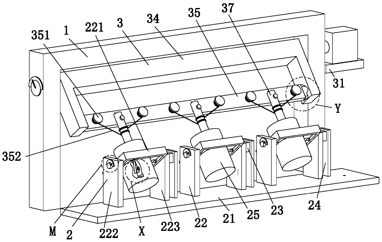
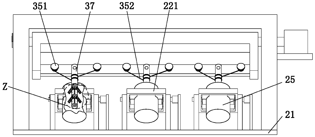
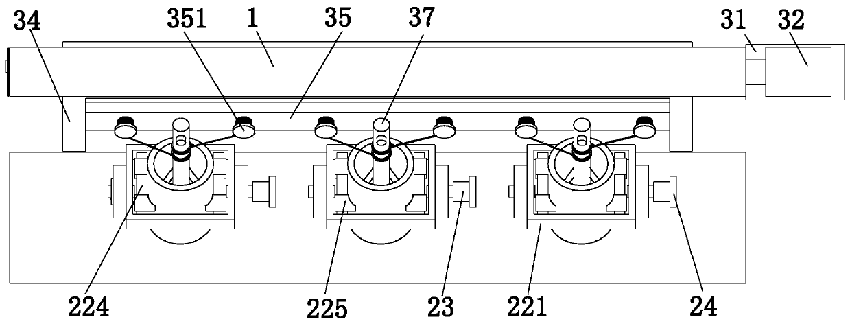
[0033] Such as Figure 1 to Figure 10 As shown, a building concrete pouring vibration machine includes a gantry 1, a clamping device 2 and a vibration device 3. The front side of the gantry 1 is provided with a clamping device 2, and the gantry 1 is fitted by sliding The vibration device 3 is installed in the way, and the clamping device 2 is connected with the vibration device 3 through a sliding fit.

[0034] The clamping device 2 includes a base 21, a clamping group 22, a No. 1 motor 23, a mounting plate 24 and a pouring workpiece 25, and the upper end of the base 21 is equipped with a clamping group 22 equidistant from left to right, and the clamping group 22 The right end of the first motor 23 is mounted on the right end of the first motor 23...


PUM


Abstract

The invention relates to a building concrete pouring jolt-ramming machine. The building concrete pouring jolt-ramming machine comprises a portal frame, a clamping device and a jolt-ramming device; theclamping device is arranged on the front side of the portal frame; the jolt-ramming device is arranged on the portal frame in a sliding matched way; the clamping device is connected with the jolt-ramming device through a sliding matched mode; the jolt-ramming device adopts an adjustable structure, the rotating angle of a reverse U-shaped rotating plate can be controlled accurately by virtue of anangle device, and the rotating angle of a vibrating rod can be adjusted according to requirements, so that the depth of the vibrating rod in concrete is increased, the jolt-ramming range is enlargedand the jolt-ramming effect is improved.

Description

technical field [0001] The invention relates to the field of concrete mixing machinery, in particular to a vibrating machine for building concrete pouring. Background technique [0002] Concrete is one of the most important building materials in the world today. It is frequently used in shops, restaurants, housing and other fields. The use of this material has a long history. With the development of modern technology, whether in There has been a great leap in material performance and construction technology. Concrete is a magical material that can be applied to various technologies and environments. Its different colors, materials and elements can be enlarged cheaply. Mass production or fine manufacturing requires concrete to be compacted in some environments. Vibration is a project to make concrete more precise. The degree of compaction of concrete directly affects the strength, impermeability and frost resistance of concrete. Performance has a great impact on the construc...

Claims


Application Information

Patent Timeline
IPC IPC(8): B28B1/093
CPCB28B1/0935
Inventor 郭金生王林
Owner 黑龙江省铁投预制构件有限公司
Features
  • R&D
  • Intellectual Property
  • Life Sciences
  • Materials
  • Tech Scout
  • Unparalleled Data Quality
  • Higher Quality Content
  • 60% Fewer Hallucinations
Learn More