Braking system and method for hoisting mechanism of dynamic compaction machine

A technology for hoisting and braking systems of a dynamic compactor, which is applied in the sequence/logic controller for program control, mechanical equipment, soil protection, etc., which can solve the problem of rope disorder or rope bite, insufficient braking speed, and large acceleration value. and other problems, to achieve the effect of small free extension, good braking reliability and stable braking

Active Publication Date: 2021-08-13
长沙中能装备制造有限公司
View PDF5 Cites 0 Cited by
  • Summary
  • Abstract
  • Description
  • Claims
  • Application Information

AI Technical Summary

Problems solved by technology

[0003] At present, non-decoupling dynamic tamping machines in the industry generally use high-speed hoists to lift and lower the rammer. When the rammer falls, the hoist is driven to rotate quickly to release the rope. After the rammer falls to the ground, the hoist is braked. However, due to There is a large inertia of the winch, and the speed of the winch is very high during the lowering of the rammer. When braking, it is easy to cause the steel wire rope to protrude too much and cause rope chaos or rope biting. Some foreign equipment adopts a clutch with high reliability and has a high control The dynamic performance of the winch solves the problem of easy to mess up and bite the rope, but the overall cost is high and the braking is not fast enough
[0004] For rapid braking when the rammer touches the ground, it is first necessary to accurately judge the time when the rammer touches the ground. At present, there are two main schemes: one is to assemble a rotary encoder on the reel to record the rotational encoding at the moment the rammer leaves the ground The data of the rotary encoder is detected in real time during the falling process of the rammer, and compared with the data at the moment when the rammer leaves the ground, it is used to judge the grounding time when the rammer falls. Reliability and response speed requirements are very high, and the existing rotary encoders and controllers are difficult to meet this requirement, resulting in the low reliability of this type of dynamic compaction machine produced by domestic main engine manufacturers; another solution is to assemble on the rammer The acceleration sensor can judge the grounding time of the rammer when it detects a sudden change in the acceleration of the rammer during the falling process of the rammer. Very easily damaged, and the output data of the sensor is also easily distorted
In addition, if the sensor adopts a wired method, since the sensor signal line must be laid along the wire rope, it is easy to be damaged; while if a wireless sensor is used, the sensor must have its own power supply, and it is more likely to be damaged under high impact conditions

Method used


Image

  • Braking system and method for hoisting mechanism of dynamic compaction machine
  • Braking system and method for hoisting mechanism of dynamic compaction machine
  • Braking system and method for hoisting mechanism of dynamic compaction machine

Examples


Embodiment 1

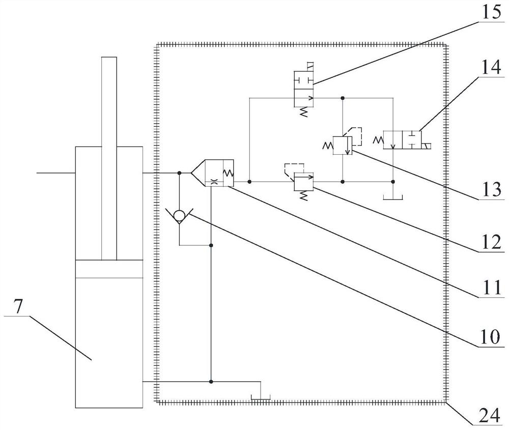
[0036] The braking system of the lifting mechanism of the dynamic compaction machine includes sensors, control systems, and hydraulic control circuits.

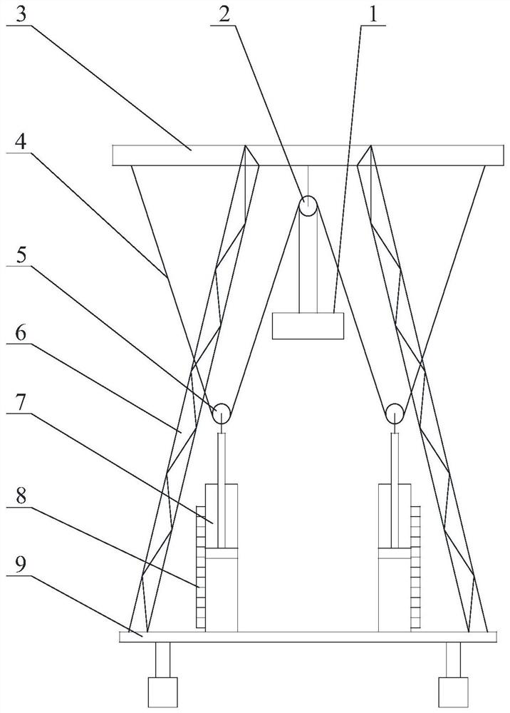
[0037]In order to describe the present invention in more detail, in this embodiment, a detailed description will be given in conjunction with the actual design and use of the dynamic compaction machine of the present invention. The dynamic tamping machine comprises a chassis, a side support, and a top beam, and the four side supports are annularly arranged on the chassis, and the top beam is fixedly connected with the tops of the four side supports. The two lifting cylinders are symmetrically arranged, and the lifting cylinders are installed on the side bracket or the chassis, and can be installed vertically or inclined along the side bracket. The piston rod of the lifting cylinder is connected to the movable pulley, and the fixed pulley is installed on the top beam. One end of the hoisting rope goes around the fixed pulley a...

Embodiment 2

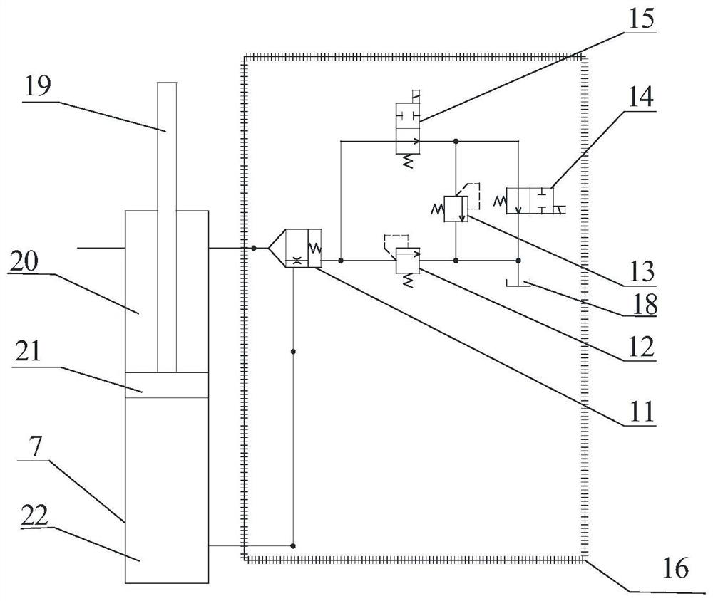
[0055] In this embodiment, only the method for determining the time when the rammer starts to touch the ground and the structure adopted are slightly different, and the others are the same as those in Embodiment 1, and the present embodiment will not repeat them for the similarities.

[0056] In this embodiment, the sensor is an acceleration sensor. The stroke sensor is not installed at the lifting cylinder, but the acceleration sensor is installed on the piston or piston rod or the movable pulley of the lifting cylinder, and the acceleration sensor is electrically connected with the control system.

[0057] Correspondingly, in this embodiment, only steps S1 and S2 are slightly different in the braking method of the hoisting mechanism of the dynamic compaction machine, and the working principle and working process of the other hydraulic control circuits including S1 and S2 are the same.

[0058] Among them, S1: the control system issues a command to lift the rammer. After the ...


PUM


Abstract

The brake system of the lifting mechanism of the dynamic compaction machine is used to detect the sensor (8) of the motion signal of the lifting cylinder, and the sensor (8) is installed on the lifting cylinder (7); it is used to control the movement and braking of the lifting cylinder (7). The hydraulic control circuit (24), the hydraulic control circuit (24) is connected to the lifting cylinder (7); the control mechanism for receiving and processing the signal transmitted by the sensor (8) and controlling the working state of the hydraulic control circuit (24), the sensor ( 8), the hydraulic control circuit (24) is all electrically connected with the control mechanism. The braking method of the lifting mechanism of the dynamic compaction machine adopts the braking system of the lifting mechanism of the dynamic compaction machine. The invention has the advantages of stable braking and faster braking of the lifting mechanism. The invention belongs to the technical field of dynamic compactors.

Description

technical field [0001] The invention belongs to the technical field of dynamic compaction machines, and in particular relates to a braking system and method for a lifting mechanism of a dynamic compaction machine. Background technique [0002] For the non-decoupling dynamic tamping machine, after the rammer falls to the ground during construction, in order to prevent the steel wire rope from continuing to protrude too much due to the inertia of the structural parts, causing many problems such as rope disorder and rope biting; Braking starts when it touches the ground, which may cause the boom to break or roll over. Therefore, it is necessary to accurately judge the time when the tamper hammer touches the ground and brake the rammer lifting mechanism reliably. That is, fast and reliable braking needs to be realized for the non-decoupling type dynamic compaction machine. [0003] At present, non-decoupling dynamic tamping machines in the industry generally use high-speed hois...

Claims


Application Information

Patent Timeline
Patent Type & Authority Patents(China)
IPC IPC(8): G05B19/04E02D3/046F15B11/08
CPCE02D3/046F15B11/08
Inventor 石培科王美成孔国华张作良
Owner 长沙中能装备制造有限公司
Why Eureka
Try Eureka