Blade boundary layer suction jet device

A technology of a jet device and a boundary layer, which is applied to the components of a pumping device for elastic fluids, fluid flow, non-variable-capacity pumps, etc., can solve the problems of unsustainable jet flow, inconvenient control of the size and direction of the jet, etc. , to achieve the effect of convenient control and simple control method

Active Publication Date: 2020-01-14
WUHAN UNIV
View PDF13 Cites 2 Cited by
  • Summary
  • Abstract
  • Description
  • Claims
  • Application Information

AI Technical Summary

Problems solved by technology

The jets of the traditional zero-propellant jet flow control technology are usually distributed in dots. If a large area is required to cover the surface of the blade, multiple zero-propellant jet actuators

Method used


Image

  • Blade boundary layer suction jet device
  • Blade boundary layer suction jet device
  • Blade boundary layer suction jet device

Examples


Example Embodiment

[0021] In order to better understand the present invention, the following examples are further descriptions of the present invention, but the content of the present invention is not limited to the following examples.
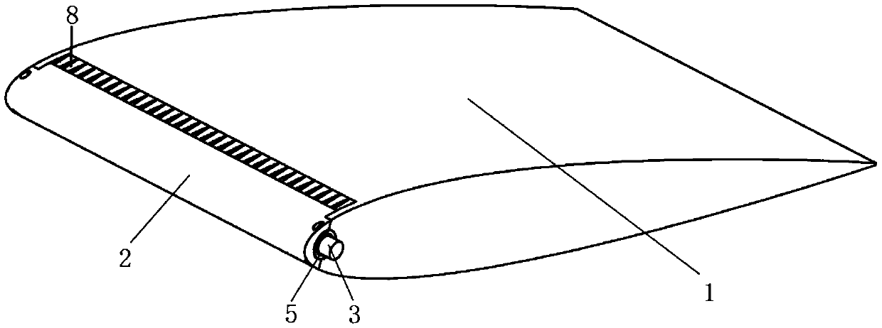
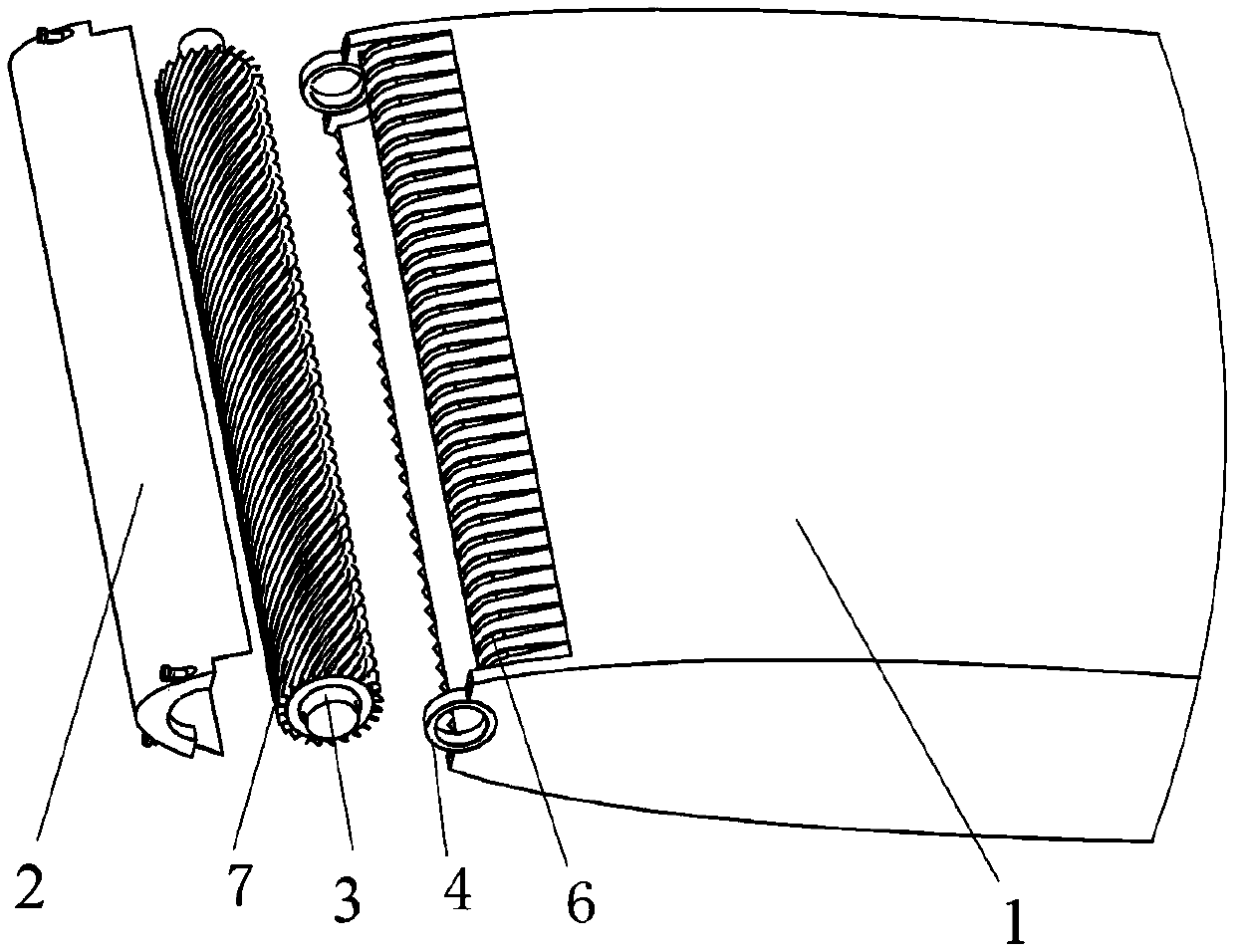
[0022] The present invention provides a suction jet device for the surface layer of a blade, such as figure 1 with figure 2 As shown, it includes a blade body 1, a rotor 3 rotatably arranged on the air inlet and outlet ends of the blade body 1, and an arc-shaped blade leading edge 2 that covers the rotor 3 and is fixedly connected to the blade body 1. The upper surface and the lower surface of the blade body 1 are both arc-shaped structures (the descriptions of "up, down, clockwise, counterclockwise" in this embodiment are all for the drawings in the specification, and are not intended to limit the present invention. ). The two sides of the air inlet and outlet ends of the blade body 1 are respectively fixedly provided with a bearing seat 4, each bearing seat 4 is...


PUM


Abstract

The invention relates to a blade boundary layer suction jet device. The blade boundary layer suction jet device comprises a blade body, a rotor rotationally arranged on the airflow inlet and outlet end of the blade body and an arc-shaped blade leading edge covering the rotor and fixedly connected to the blade body. A plurality of stationary blade flow passages are arranged on the surface of the airflow inlet and outlet end of the blade body side by side. A plurality of spiral moving blade runners with the axis of the rotor as the center are arranged on the surface of the rotor. The stationaryblade runners are in one-to-one correspondence with the moving blade runners, the blade leading edge is fixed to the blade body, then a first gap for airflow inlet/outlet is formed between the blade leading edge and one surface of the blade body, a second gap for airflow inlet/outlet is formed between the blade leading edge and the other opposite surface of the blade body, and the first gap and the second gap both are communicated with the stationary blade runners. According to the blade boundary layer suction jet device, the stable and continuous jet can be obtained by driving the rotor to rotate through one driving source, the size and the direction of the jet are changed by controlling the rotating speed and direction of the rotor, and the control method is simple,

Description

technical field [0001] The invention relates to the technical field of active flow control, in particular to a suction jet device based on zero working fluid jet and applied to blades. Background technique [0002] Flow separation is a very important and complex flow phenomenon in fluid mechanics, which is commonly found in various practical projects such as aerospace and power machinery. In many power machines, fluid separation from solid wall surfaces is unavoidable. Although separated flow can improve heat and mass transfer and mixing efficiency, it often causes a large amount of energy loss due to its inherent unsteadiness. Flow separation will not only increase the resistance of the aircraft, reduce the lift force, cause backflow or even stall, but also reduce the operating efficiency of the power machinery, cause the power machinery to vibrate, and endanger the safe operation of the unit. For example, in an axial flow compressor, the separation of the flow around the...

Claims


Application Information

Patent Timeline
IPC IPC(8): F15D1/00F04D29/32F04D29/66
CPCF04D29/324F04D29/666F15D1/00
Inventor 姜伟谢诞梅岳亚楠杜海芬梅子岳吴凡
Owner WUHAN UNIV
Why Eureka
Try Eureka