
Metering equipment fault detection method based on AR technology

A metering equipment and fault detection technology, which is applied in the direction of calculation, measuring devices, and measuring electrical variables, etc., can solve the problems of limited technical level and experience of meter reading operation and maintenance personnel, high operation and maintenance costs, and failure to eliminate hidden dangers of equipment in time. Achieve the effect of improving operation and maintenance work efficiency and reducing technical requirements

Inactive Publication Date: 2020-01-14
GUIZHOU POWER GRID CO LTD
View PDF5 Cites 8 Cited by
  • Summary
  • Abstract
  • Description
  • Claims
  • Application Information

AI Technical Summary

Problems solved by technology

[0002] With the full coverage of metering equipment such as smart meters and low-voltage centralized reading, the task of operation and maintenance of low-voltage centralized reading is very arduous. The whole process of maintenance work cannot be effectively supervised, and there is an urgent need to use new technologies to improve the efficiency of operation and maintenance of metering equipment
[0003] At present, the meters of low-voltage centralized reading terminals are huge in scale, of various types, and updated quickly. Traditional operation and maintenance require manual on-site inspections. Only through on-site inspections and understanding of fault phenomena can a maintenance plan be proposed.
However, paper records are used in the maintenance process, the data correlation is poor, and it is difficult to make statistical analysis. In addition, the number of experts is limited, so it is impossible to provide on-site assistance and eliminate hidden dangers in time, resulting in high operation and maintenance costs.

Method used


Image

  • Metering equipment fault detection method based on AR technology
  • Metering equipment fault detection method based on AR technology
  • Metering equipment fault detection method based on AR technology

Examples


Embodiment 1

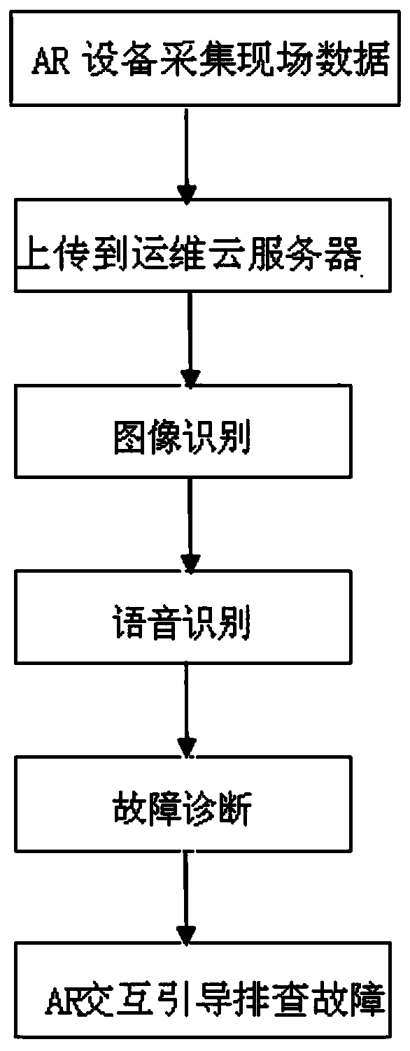
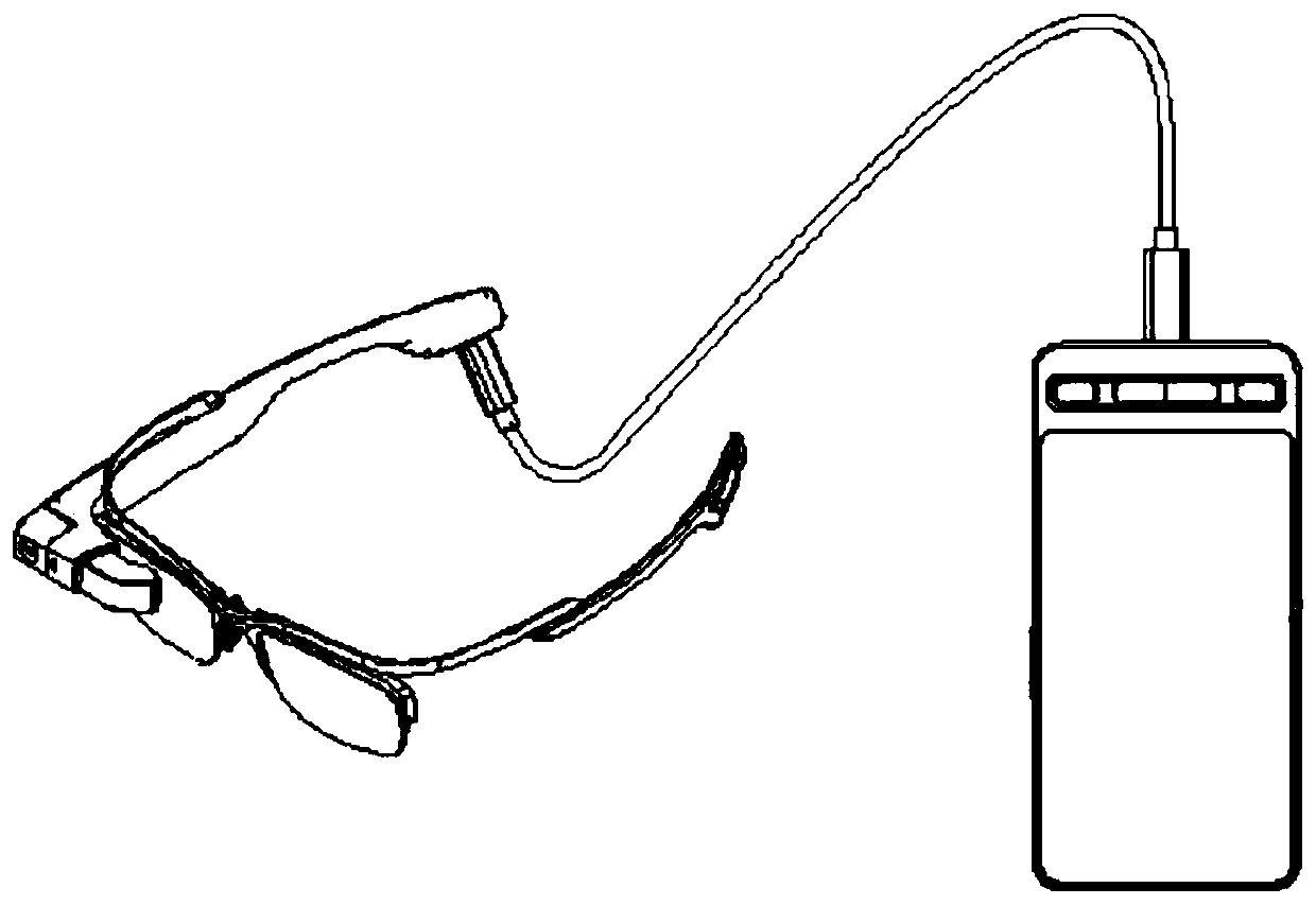
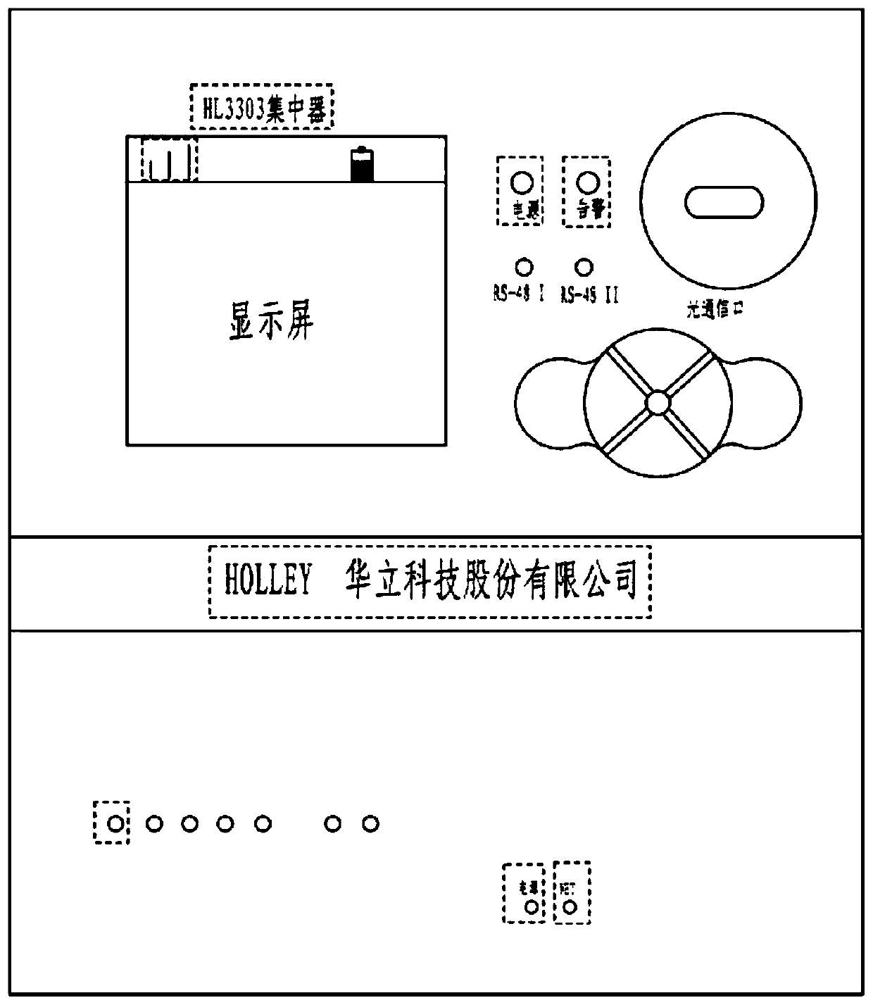
[0027] Example 1: Such as Figure 1-4 As shown, an AR technology-based fault detection method for metering equipment includes the following steps:

[0028] (1) Offline construction of image recognition engine: Collect more than 5,000 pieces of on-site equipment image material marking features, and import more than 5,000 pieces of on-site equipment image materials through image deep learning training tools. The image materials include normal operation of the on-site equipment and various fault conditions. , Mark the characteristics of each picture, the characteristics of each picture include the name of the manufacturer, model, power light, running light, LCD screen and barcode, and use the YOLO algorithm to train the image recognition model of measurement equipment;

[0029] (2) Offline construction of fault diagnosis expert knowledge base: according to the standardization and safety requirements of power equipment operation and maintenance operations, establish a standardized know...


PUM


Abstract

The invention discloses a metering equipment fault detection method based on an AR technology. The method comprises: using AR equipment for collecting environmental data in an operation and maintenance site, extracting an equipment model through an image recognition technology, conducting intelligent visual fault judgment according to information such as an equipment indicator lamp, and then the equipment entering an expert database to retrieve related faults; and if the related data is retrieved, superposing the key points for troubleshooting into a real scene through an equipment model generated by the AR equipment to guide field maintenance personnel to troubleshoot; and if a fault which cannot be confirmed is preliminarily judged by depending on image recognition, performing knowledgeretrieval on the expert database by using voice (retrieval requirements are submitted to the expert database after keywords are recognized by a voice recognition engine). The method is applied to field fault detection of metering equipment, the technical requirements for operation and maintenance personnel are reduced, and the operation and maintenance work efficiency is improved.

Description

Technical field [0001] The invention belongs to the technical field of low-voltage operation and maintenance, and specifically relates to a method for detecting faults of metering equipment based on AR technology. Background technique [0002] As smart meters and low-voltage centralized reading and other metering equipment will achieve full coverage, the task of low-voltage centralized reading operation and maintenance is very difficult, mainly because the original meter reading operation and maintenance personnel have limited technical level and experience, and the operation and maintenance records are inconvenient for statistical analysis and operation. The whole process of maintenance work cannot be effectively supervised and other issues. New technologies are urgently needed to improve the efficiency of operation and maintenance of metering equipment. [0003] At present, low-voltage centralized reading terminal meters are large in scale, diverse in types, and quick to update. ...

Claims


Application Information

Patent Timeline
Patent Type & Authority Applications(China)
IPC IPC(8): G06Q10/00G06F16/33G06K9/00G06K9/62G01R35/04
CPCG06Q10/20G06F16/3343G01R35/04G06V20/10G06F18/214
Inventor 张秋雁张俊玮丁超黎世华王铎润王蓝苓李航峰高承贵张海永钱威张驰黄宸希
Owner GUIZHOU POWER GRID CO LTD
Learn More