Injection mold provided with anti-jamming mechanism
An injection mold and anti-jamming technology, which is applied in the field of mold processing and manufacturing, can solve the problems that the mold cannot be automatically discharged, manually taken out, scalded, etc., and achieves the effects of ensuring injection molding production operations, avoiding gaps, and high mold production efficiency
- Summary
- Abstract
- Description
- Claims
- Application Information
AI Technical Summary
Problems solved by technology
Method used
Image
Examples
specific Embodiment approach 1
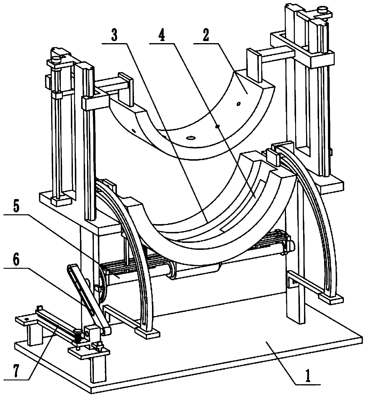
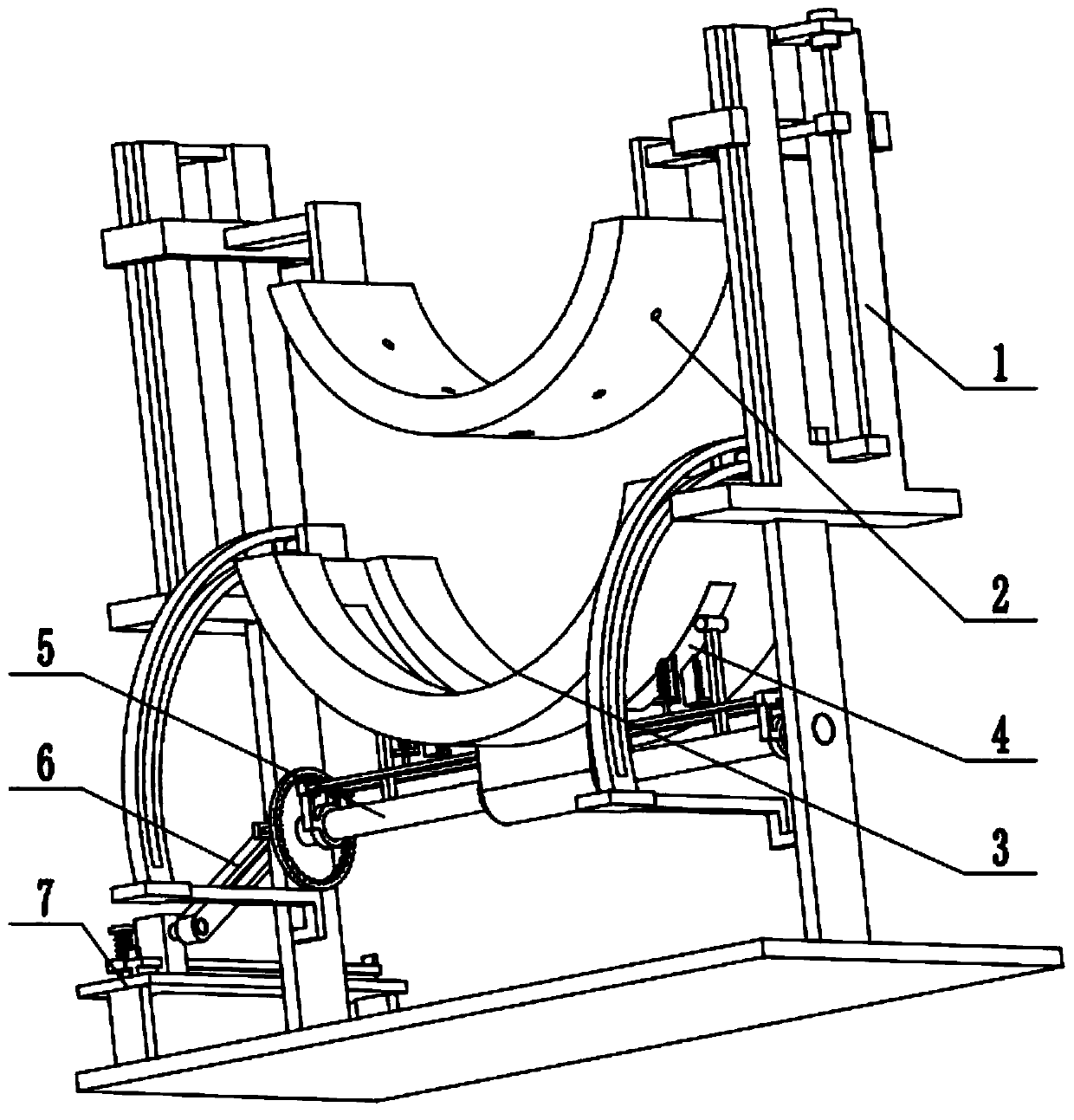
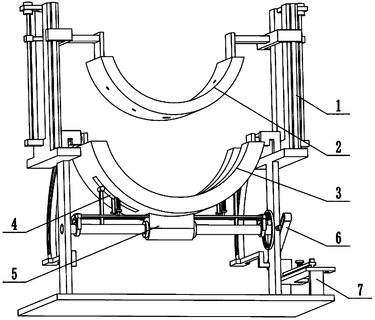
[0029] Combine below Figure 1-11 Describe this embodiment, an injection mold with an anti-seize mechanism, including a frame 1, a movable mold assembly 2, a fixed mold assembly 3, a mold ejection mechanism 4, a rotary demoulding control mechanism 5, and a rotary control mechanism 6 and the rotary control mechanism sliding seat 7, the movable mold assembly 2 is arranged on the upper end of the frame 1, the fixed mold assembly 3 is arranged on the middle part of the frame 1, and the mold ejection mechanism 4 is provided with two, two molds The ejector mechanism 4 is symmetrically arranged on the fixed mold assembly 3, the rotary demoulding control mechanism 5 is arranged on the frame 1, the rotary demoulding control mechanism 5 is located below the fixed mold assembly 3, and the upper end of the rotary demoulding control mechanism 5 Fitted with two mold ejection mechanisms 4, the rotation control mechanism 6 is connected to the left side of the rotation control mechanism 5, the...
specific Embodiment approach 2
[0031] Combine below Figure 1-11 To illustrate this embodiment, the frame 1 includes a base plate 1-1, a support plate 1-2, a horizontal frame plate 1-3, a U-shaped seat plate 1-4, a raised rail 1-5, and a motor 1-6 and lead screw 1-7; base plate 1-1 is fixedly connected with two support plates 1-2, two support plates 1-2 are respectively fixedly connected with a horizontal frame plate 1-3, and two horizontal frame plates 1-3 are fixedly connected One U-shaped seat plate 1-4 is fixedly connected respectively, and the two motors 1-6 are respectively fixedly connected to the two U-shaped seat plates 1-4 through the motor frame, and the output shafts of the two motors 1-6 are respectively passed through the coupling A lead screw 1-7 is connected; a convex slide rail 1-5 is respectively arranged at the front and rear ends of the two U-shaped seat plates 1-4.
specific Embodiment approach 3
[0033] Combine below Figure 1-11 To illustrate this embodiment, the movable mold assembly 2 includes a movable mold 2-1, an injection hole 2-2, a vent hole 2-3, a fixed plate 2-4, a connecting plate 2-5, and a U-shaped sliding seat 2- 6. The connecting rod 2-7 and the linkage block 2-8; the middle part of the movable mold 2-1 is provided with an injection hole 2-2, and the movable mold 2-1 is symmetrically provided with a plurality of ventilation holes 2-3, and the movable mold 2-1 The two ends of 1 are respectively fixedly connected to a fixed plate 2-4, and the two fixed plates 2-4 are respectively fixedly connected to a connecting plate 2-5, and the two connecting plates 2-5 are respectively fixedly connected to a U-shaped sliding seat 2- 6. The inner sides of the two U-shaped sliding seats 2-6 are respectively fixedly connected to a connecting rod 2-7, and the two connecting rods 2-7 are respectively fixedly connected to a linkage block 2-8, and the two linkage blocks 2-8...
PUM
 Abstract
Description
Claims
Application Information
 - R&D
- Intellectual Property
- Life Sciences
- Materials
- Tech Scout
- Unparalleled Data Quality
- Higher Quality Content
- 60% Fewer Hallucinations
Browse by: Latest US Patents, China's latest patents, Technical Efficacy Thesaurus, Application Domain, Technology Topic, Popular Technical Reports.
© 2025 PatSnap. All rights reserved.Legal|Privacy policy|Modern Slavery Act Transparency Statement|Sitemap|About US| Contact US: help@patsnap.com


