Kinematics assembly

A technology for moving components and guides, applied in vehicle components, transportation and packaging, heating/cooling equipment, etc., can solve the problem that the installation process cannot use process reliability configuration, etc., and achieve the effect of precise actuation and simple cost.

Inactive Publication Date: 2020-01-17
MAHLE INT GMBH
View PDF0 Cites 0 Cited by
  • Summary
  • Abstract
  • Description
  • Claims
  • Application Information

AI Technical Summary

Problems solved by technology

[0004] However, the disadvantage of the previous solutions is that there is a relatively large tolerance chain between the tongues of the bearing plate, the housing and the cam disc, whereby the entire assembly process cannot be configured with process reliability

Method used


Image

  • Kinematics assembly
  • Kinematics assembly

Examples


Embodiment Construction

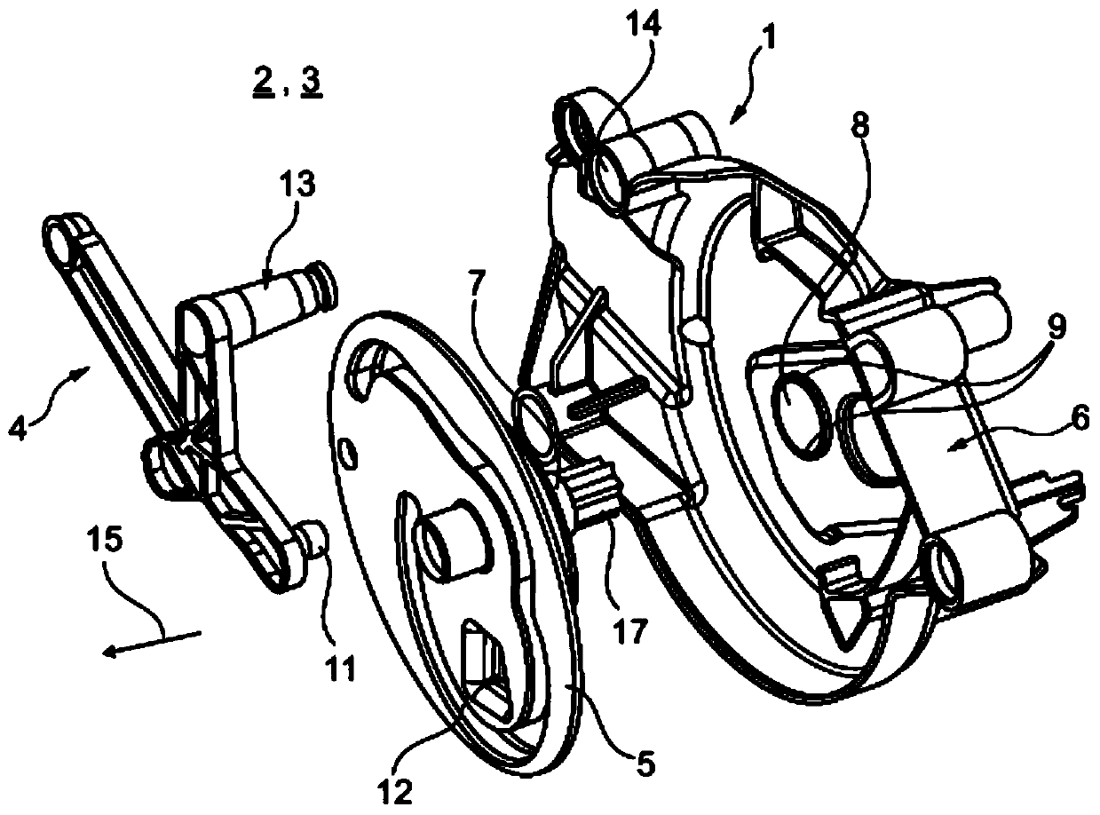
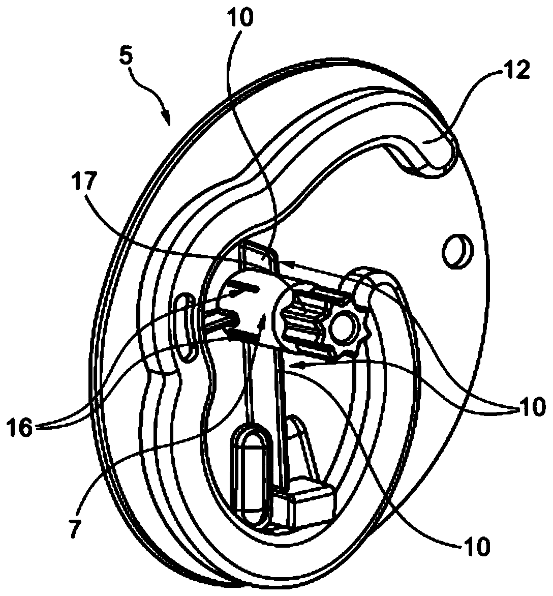
[0021] according to figure 1 , the moving assembly 1 of the air conditioning system 2 for a motor vehicle 3 according to the invention (which is not shown in further detail) has a control lever 4 for driving, in particular a damper (not shown), a cam disc 5 and a bearing plate 6 . The cam disc 5 here has bearing pins 7 (see also figure 2 ), while the bearing plate 6 has a bearing opening 8 in which the cam disc 5 is mounted in a torque-resistant manner by means of its bearing pin 7 in the mounting position and is rotatably mounted in the operating position. According to the invention, at least one groove 9, here two grooves 9, is provided at the bearing opening 8, wherein at least one tongue 10 formed in a complementary manner to the groove 9 is arranged on the bearing pin 7 of the cam disc 5, It is two tongues 10 in the text. In the predefined mounting position, the cam disc 5 is in this context with its tongue 10 (ie tongues 10 in the present case) entering into the asso...


PUM


Abstract

The invention relates to a kinematics assembly which may include a control lever configured to drive a plurality of air flaps, a cam disc, and a bearing plate. The cam disc may include a bearing pin and the bearing plate may have a bearing opening in which the cam disc is mounted via the bearing pin. At least one groove may be disposed at the bearing opening. The bearing pin may include a tongue structured in a complementary manner to the at least one groove. The cam disc may be rotationally fixed to the bearing plate in a predefined mounting position in which the tongue is engaged in the at least one groove. The cam disc may be rotatably mounted on the bearing plate in an operating position in which the cam disc is displaced in an axial direction such that the tongue is not engaged in theat least one groove.

Description

technical field [0001] The invention relates to a kinematic assembly with a control rod for driving, in particular a damper. Furthermore, the invention relates to an air conditioning system with such a moving assembly and a motor vehicle with such an air conditioning system. Background technique [0002] A kinematic assembly comprising at least one bearing plate, a cam disc and a control lever for actuating at least one damper, wherein such a kinematic assembly is usually prefabricated and subsequently installed in an air conditioning system, and in doing so, is in operative connection with the damper to be actuated . In order to simplify the installation, the installation positions where the kinematic components are to be installed are predetermined here for the cam disc and the control lever. Subsequent installation of the kinematic components at the installation location, wherein the fixing of the installation point is usually omitted until the installation, can lead to...

Claims


Application Information

Patent Timeline
Patent Type & Authority Applications(China)
IPC IPC(8): B60H1/00B60H1/34
CPCB60H1/0065B60H1/34B60H2001/3478B60H1/00857B60H1/00564B60H1/00671B60H2001/00707
Inventor 劳夫·赖因
Owner MAHLE INT GMBH
Why Eureka
Try Eureka