
Protection device for sealing gate grooves of diversion tunnel

A protection device and gate slot technology, which is applied in coastline protection, water conservancy engineering, sea area engineering, etc., can solve the problems of poor flow state at the bottom of the gate slot, long diversion time, and large vibration at the bottom of the gate, so as to achieve smooth flow state, Good vibration resistance

Pending Publication Date: 2020-01-17
CHINA POWER CONSRTUCTION GRP GUIYANG SURVEY & DESIGN INST CO LTD
View PDF0 Cites 0 Cited by
  • Summary
  • Abstract
  • Description
  • Claims
  • Application Information

AI Technical Summary

Problems solved by technology

[0002] For the diversion tunnel plugging gate, in order to improve the hydraulic flow state of the gate slot, the gate slot usually adopts type II, but because the construction diversion time is generally long, the gate slot is easy to be damaged under the long-term erosion of the water flow, especially the The impact of sand and gravel on the gate slot is more likely to damage the gate slot, resulting in poor flow state at the bottom of the gate slot when the lower gate is storing water, and the lower gate of the gate vibrates greatly and is easy to jam. In addition, after the gate is lowered, the water seal device and Poor contact and serious water leakage of the gate slot track will lead to greater difficulty in the construction of the plug; although there are some projects in the prior art that diversion tunnels are blocked and the gate slots are equipped with protective devices, they are basically placed on the frame set by section steel or angle steel. In the door slot, the water flow will enter the door slot to form a backflow, which will easily damage the frame, and it is not easy to lift it out when the diversion hole is blocked to store water in the lower gate; therefore, the existing technology is not perfect enough and needs to be further improved

Method used


Image

  • Protection device for sealing gate grooves of diversion tunnel
  • Protection device for sealing gate grooves of diversion tunnel

Examples


Embodiment Construction

[0013] The present invention will be further described in detail below in conjunction with the accompanying drawings and embodiments.

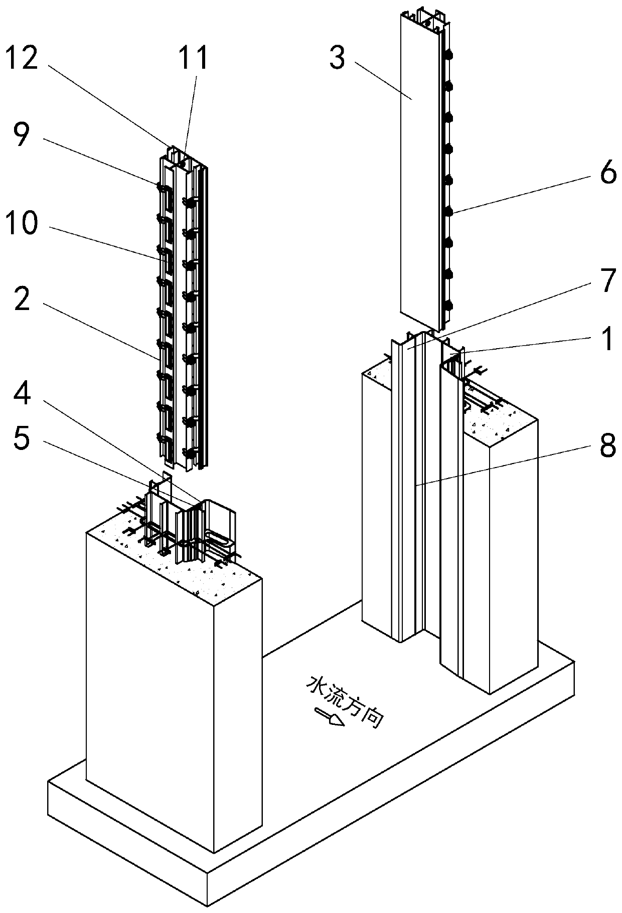
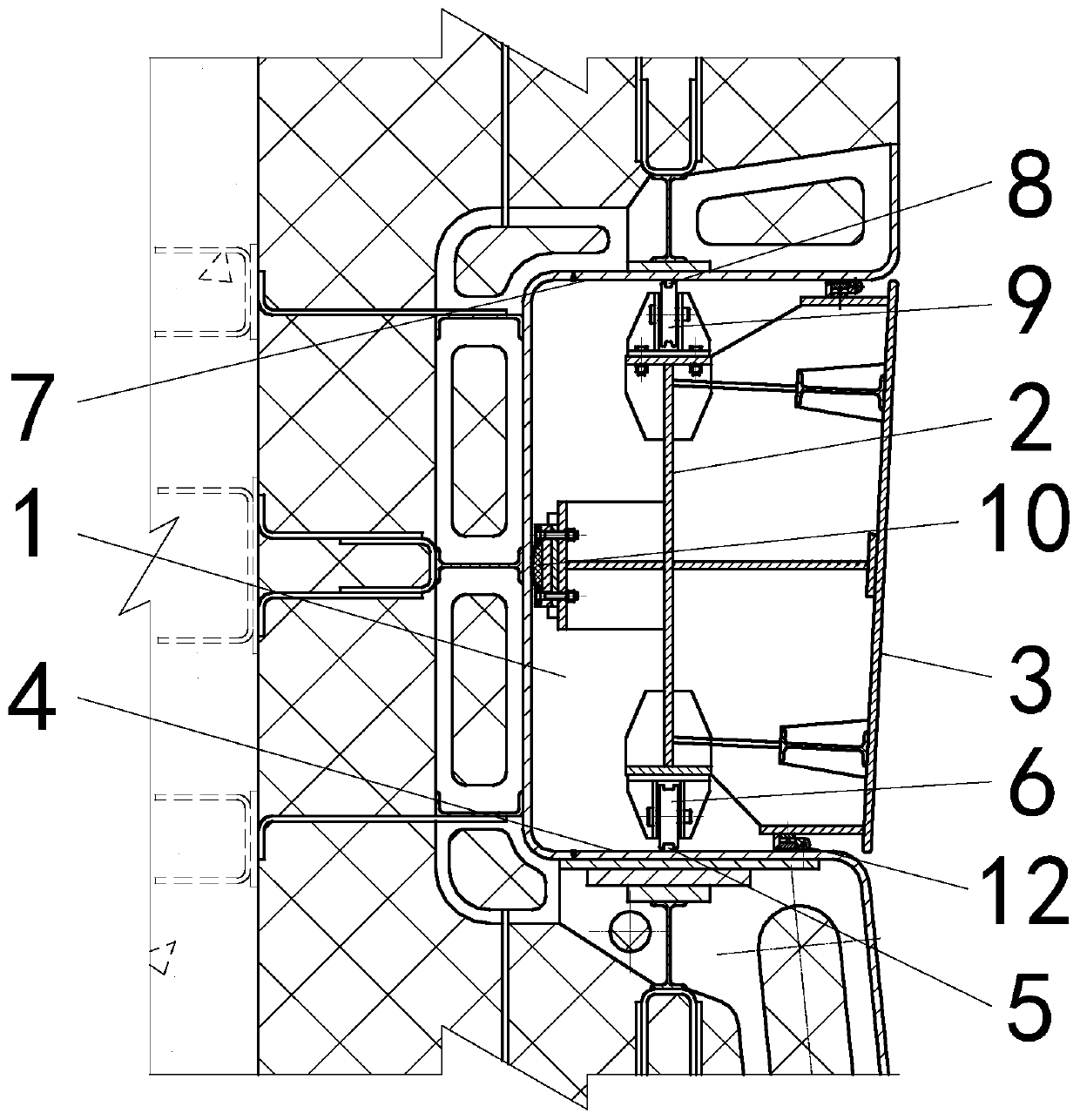
[0014] A protection device for diversion tunnel blocking gate groove of the present invention, such as figure 1 with figure 2 As shown, it includes a pair of protection devices 2 symmetrically arranged in the gate grooves 1 on both sides of the diversion tunnel; water retaining panels 3 are provided on the protection devices 2; The main side groove type fixed wheel device 6 corresponding to the position of the main rail head 5 on the rail surface 4; the reverse side groove corresponding to the position of the anti rail head 8 on the anti rail surface 7 of the gate groove 1 is provided on the protection device 2 fixed wheel device 9; a support slideway device 10 with high bearing strength is provided on the side of the protection device 2; in order to facilitate installation, a lifting lug 11 is provided on the top of the protection device 2;...


PUM


Abstract

The invention discloses a protection device for sealing gate grooves of a diversion tunnel. The protection device for the sealing gate grooves of the diversion tunnel comprises a pair of protection devices (2) symmetrically arranged in the gate grooves (1) in the two sides of the diversion tunnel, wherein each protection device (2) is provided with a water-retaining panel (3); each protection device (2) is provided with a main-side groove-type fixed wheel device (6) corresponding to a main rail head (5) on a main rail surface (4) of the corresponding gate groove (1) in position; each protection device (2) is provided with a reverse-side groove-type fixed wheel device (9) corresponding to a reverse rail head (8) on a reverse rail surface (7) of the corresponding gate groove (1) in position;and a bearing slide way device (10) with high bearing strength is arranged on the side surface of each protection device (2). According to the protection device for the sealing gate grooves of the diversion tunnel, a smooth flow state of water flow while passing through the gate grooves is benefited, and high vibration resistance is achieved; and a lifting lug is arranged at the top of each protection device, so that firm fixing for the protection device in the corresponding gate groove is benefited, and the protection device is easily lifted out.

Description

technical field [0001] The invention relates to a protection device for diversion tunnels to block gate slots, and belongs to the technical field of metal structures of water conservancy and hydropower projects. Background technique [0002] For the diversion tunnel plugging gate, in order to improve the hydraulic flow state of the gate slot, the gate slot usually adopts type II, but because the construction diversion time is generally long, the gate slot is easy to be damaged under the long-term erosion of the water flow, especially the The impact of sand and gravel on the gate slot is more likely to damage the gate slot, resulting in poor flow state at the bottom of the gate slot when the lower gate is storing water, and the lower gate of the gate vibrates greatly and is easy to jam. In addition, after the gate is lowered, the water seal device and Poor contact and serious water leakage of the gate slot track will lead to greater difficulty in the construction of the plug;...

Claims


Application Information

Patent Timeline
Patent Type & Authority Applications(China)
IPC IPC(8): E02B7/30
CPCE02B7/30
Inventor 王兴恩
Owner CHINA POWER CONSRTUCTION GRP GUIYANG SURVEY & DESIGN INST CO LTD
Features
  • Generate Ideas
  • Intellectual Property
  • Life Sciences
  • Materials
  • Tech Scout
  • Unparalleled Data Quality
  • Higher Quality Content
  • 60% Fewer Hallucinations
Learn More