
Novel planar spring pinch valve device

A technology of planar spring and pinch valve, which is applied in the field of medical equipment to achieve the effect of reducing operating noise, small heat generation, and good stability

Pending Publication Date: 2020-01-17
北京哈特凯尔医疗科技有限公司
View PDF0 Cites 0 Cited by
  • Summary
  • Abstract
  • Description
  • Claims
  • Application Information

AI Technical Summary

Problems solved by technology

[0003] In the process of clinical use, the pinch valve of conventional technology can only clamp a medical hose with a fixed diameter in clinical application. Due to the diversity of medical equipment and the increasingly diversified treatment methods, a certain equipment needs to be In use, use the same pinch valve to pinch clinical tubing of different diameters

Method used


Image

  • Novel planar spring pinch valve device
  • Novel planar spring pinch valve device
  • Novel planar spring pinch valve device

Examples


Embodiment Construction

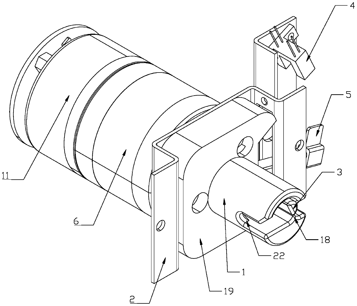
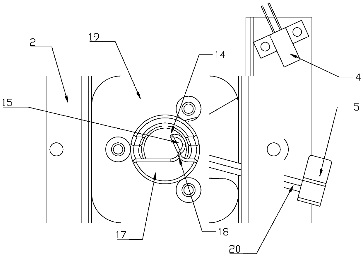
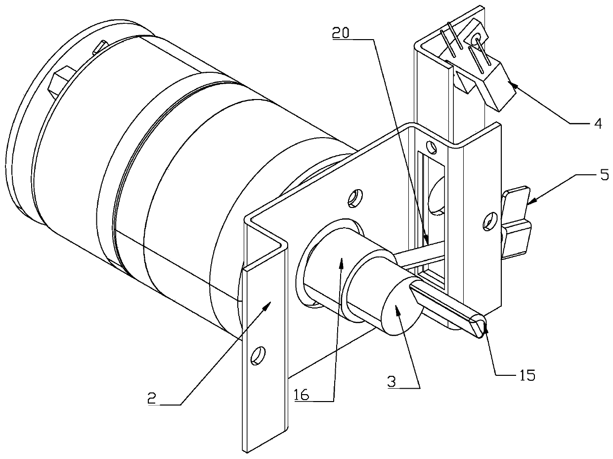
[0032] like figure 1 , figure 2 , image 3 and Figure 9 As shown, a novel plane spring pinch valve device includes an eccentric column 3 and a collet 1, and the collet 1 is provided with intersecting pipeline passages 13 ( Figure 9 shown) and opening and closing channel 14 ( figure 2 shown), one end of the eccentric column 3 is the working end 15, and the other end is the driving end 16 ( image 3 As shown), the working end 15 is located in the opening and closing channel 14, the driving end 16 drives the working end 15 to rotate forward or reverse in the opening and closing channel 14, and the working end 15 is forward When rotating, away from or against the inner wall of the pipeline channel 13 .

[0033] like Figure 7 to Figure 9 As shown, the chuck 1 is a cylindrical chuck, and a U-shaped groove 22 is opened on the wall of the first end of the cylindrical chuck; the U-shaped groove 22 is parallel to the cylinder. The axial direction of the cylindrical chuck is ...


PUM


Abstract

The invention discloses a novel planar spring pinch valve device which comprises an eccentric column and a chuck. A pipeline channel and an opening / closing channel which are crossed are arranged on the chuck. One end of the eccentric column is a working end, and the other end of the eccentric column is a driving end. The working end is located in the opening / closing channel. The driving end drivesthe working end to rotate forwards or backwards in the opening / closing channel. The working end gets away from or abuts against the inner wall of the pipeline channel when rotating forwards. By meansof the novel planar spring pinch valve device, pipelines are pinched to be closed through the elastic force of planer springs, and the pipelines with different diameters are pinched to be closed by the same device in different use environments or different use periods. An opening limit and a closing limit are arranged at the switch-on position and the pinch-switch-off position of a pinch valve, and it is avoided that the rotating position is located within an unexpected use range. A control circuit converts a large starting current into a small maintaining current according to a detected opening signal, and therefore the pinch valve is switched on through a large current, and the switch-on state of the pinch valve is maintained through a small current.

Description

technical field [0001] The invention relates to the technical field of medical instruments. Specifically, it is a novel planar spring pinch valve device. Background technique [0002] In clinical practice, when extracorporeal circulation is established through hemodialysis or when fluid is infused intravenously into the human body through other external equipment and pipelines, in order to ensure the safety of treatment, if bubbles appear during fluid transmission, the equipment can detect the bubbles and make a decision. Actuation in response causes the pinch valve to shut off fluid delivery. [0003] In the process of clinical use, the pinch valve of conventional technology can only clamp a medical hose with a fixed diameter in clinical application. Due to the diversity of medical equipment and the increasingly diversified treatment methods, a certain equipment needs to be In use, the same pinch valve is used to pinch clinical tubing of different diameters. Contents of...

Claims


Application Information

Patent Timeline
Patent Type & Authority Applications(China)
IPC IPC(8): F16K7/02F16K31/02F16K37/00
CPCF16K7/02F16K31/02F16K37/0025
Inventor 冯新庆冯庆申冯羽亮
Owner 北京哈特凯尔医疗科技有限公司
Learn More