Remote automatic dismounting device for ultrasonic probe of gas pipeline and working method

A technology for automatic disassembly and assembly of gas pipelines, applied in measuring devices, instruments, signal transmission systems, etc., can solve problems such as threats to the life safety of operators, potential safety hazards, and inconvenient operations, so as to ensure measurement accuracy, stability, and safety High performance and practical effect

Inactive Publication Date: 2020-01-17
SD STEEL RIZHAO CO LTD
View PDF5 Cites 1 Cited by
  • Summary
  • Abstract
  • Description
  • Claims
  • Application Information

AI Technical Summary

Problems solved by technology

[0002] The equipment installed on the gas pipeline to measure gas consumption often uses ultrasonic flowmeters. The ultrasonic flowmeter needs regular maintenance on the probe to ensure the accuracy and stability of the measurement. The whole process of installation needs to be completed manually, and it is difficult to grasp the insertion depth of the probe, which will cause measurement errors once it is disassembled. At the same time, gas is a highly toxic gas, and once it leaks, the life safety of the operator will be threatened; the probe of the ultrasonic flowmeter Installed on the gas pipeline, as the commissioning time increases, small deformation, corrosion, dust, etc. of the equipment often appear between the probe and the valve at the root of the pipeline, which makes it laborious to manually extract the probe from the pipeline. In addition, such equipment is generally installed in At high altitude, if the strength is not well controlled during the extraction process, there is a risk of a high-altitude fall accident; when disassembling and assembling the high-altitude probe, it is often necessary to carry various tools and equipment, which is not easy to operate. In addition, there are various Security risks

Method used


Image

  • Remote automatic dismounting device for ultrasonic probe of gas pipeline and working method
  • Remote automatic dismounting device for ultrasonic probe of gas pipeline and working method
  • Remote automatic dismounting device for ultrasonic probe of gas pipeline and working method

Examples


Embodiment Construction

[0024] The technical solutions in the embodiments of the present invention will be described clearly and completely in further detail below in conjunction with the accompanying drawings in the embodiments of the present invention. Based on the embodiments of the present invention, all other embodiments obtained by persons of ordinary skill in the art without making creative efforts belong to the protection scope of the present invention.

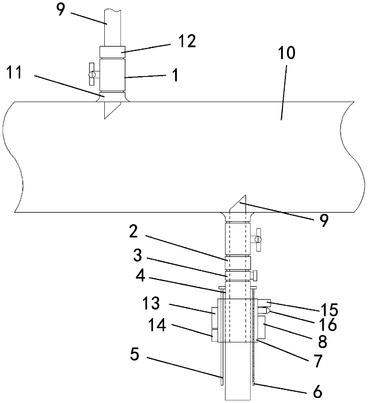
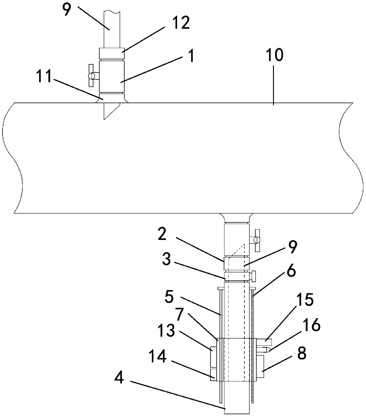
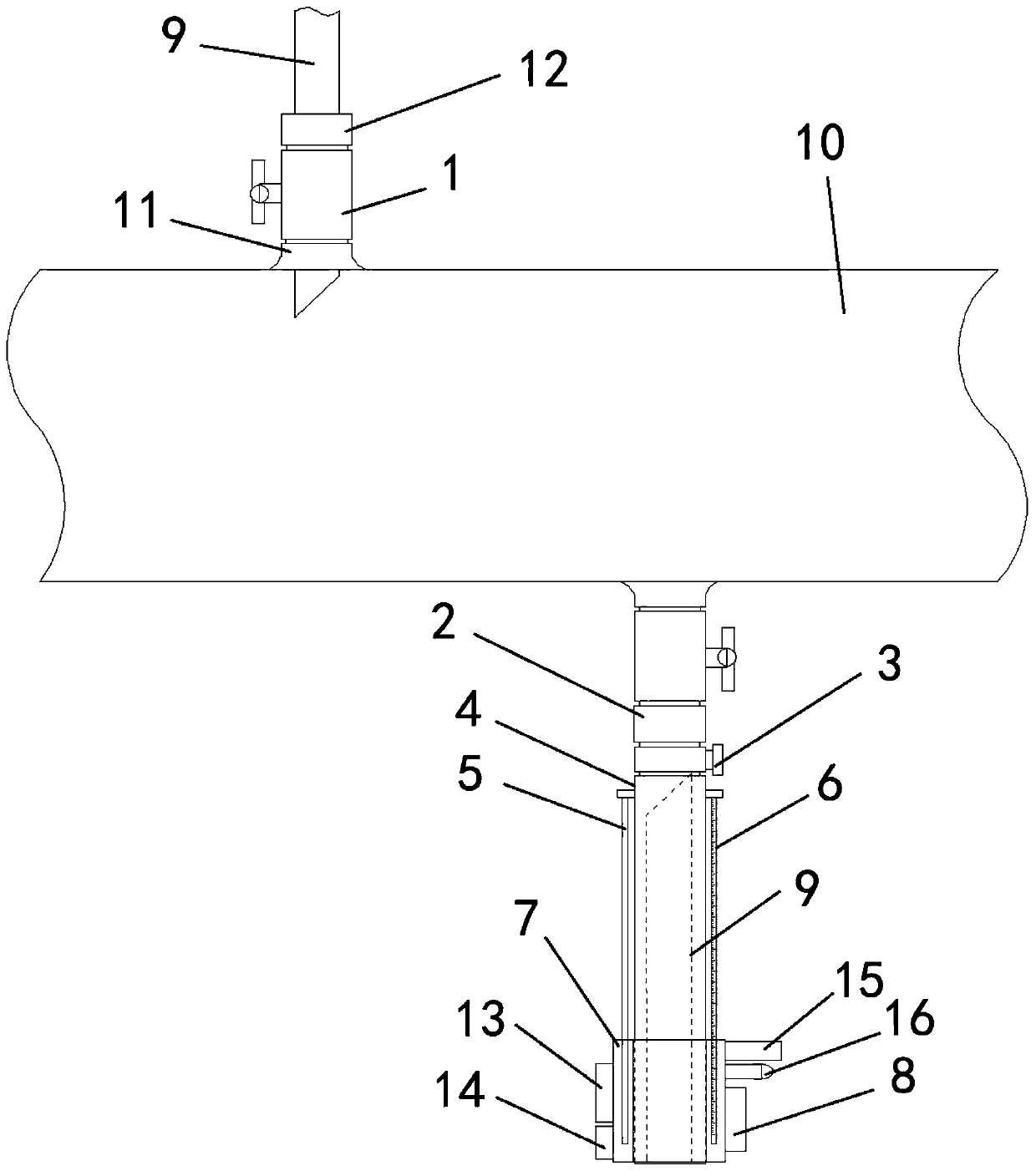
[0025] Such as Figure 1-4 As shown, a gas pipeline ultrasonic probe remote automatic disassembly device includes a gas pipeline 10, an ultrasonic probe 9 installed on the gas pipeline 10, and a movable sleeve 7 connected to the tail of the ultrasonic probe 9. The movable sleeve 7 is slidably connected to a fixed The outer side of the connection sleeve 4, the fixed connection sleeve 4 is connected to the secondary electric cut-off ball valve 3, the secondary electric cut-off ball valve 3 is connected to the root valve 1 through the joint 2, ...


PUM


Abstract

The invention discloses a remote automatic dismounting device for an ultrasonic probe of a gas pipeline and a working method. The remote automatic dismounting device comprises the gas pipeline, the ultrasonic probe mounted on the gas pipeline and a movable sleeve connected to the tail of the ultrasonic probe, wherein the movable sleeve is slidably connected to the outer side of a fixed connectingsleeve; the fixed connecting sleeve is connected to a secondary electric cut-off ball valve; the secondary electric cut-off ball valve is connected to a root valve through a connecting loose joint; the fixed connecting sleeve is connected to a fixed push-pull screw and a magnetic ruler through a connecting piece; the push-pull screw is parallel to the fixed connecting sleeve and penetrates througha screw hole of the movable sleeve; the push-pull screw is connected to a screw motor fixed to the outer wall of the movable sleeve; the magnetic ruler is parallel to the fixed connecting sleeve andpenetrates through a through hole of the movable sleeve. A controller and a display terminal designed by the invention are connected by adopting a wireless transmission module, so that an operator remotely controls the ultrasonic probe, personal injury caused by gas leakage and high-altitude operation is avoided, and the remote automatic dismounting device is high in safety and high in practicality.

Description

technical field [0001] The invention relates to the technical field of ultrasonic measurement, in particular to a remote automatic dismounting device and working method for an ultrasonic probe of a gas pipeline. Background technique [0002] The equipment installed on the gas pipeline to measure gas consumption often uses ultrasonic flowmeters. The ultrasonic flowmeter needs regular maintenance on the probe to ensure the accuracy and stability of the measurement. The whole process of installation needs to be completed manually, and it is difficult to grasp the insertion depth of the probe, which will cause measurement errors once it is disassembled. At the same time, gas is a highly toxic gas, and once it leaks, the life safety of the operator will be threatened; the probe of the ultrasonic flowmeter Installed on the gas pipeline, as the commissioning time increases, small deformation, corrosion, dust, etc. of the equipment often appear between the probe and the valve at the...

Claims


Application Information

Patent Timeline
Patent Type & Authority Applications(China)
IPC IPC(8): G01F1/66G01F15/00G01F15/06G08C17/02
CPCG01F1/66G01F15/00G01F15/061G08C17/02
Inventor 齐滨殷世宏崔国光施汉生刘文达韦涛孙洪林葛慧张育鸣秦虹周旭
Owner SD STEEL RIZHAO CO LTD
Why Eureka
Try Eureka