
Leakage testing device and leakage testing method

A leak test, tested technology, used in measuring devices, fluid tightness testing, machine/structural component testing, etc., to solve problems such as leakage, low efficiency, and long waiting time for stabilization

Inactive Publication Date: 2020-01-17
ZOOMLION HEAVY IND CO LTD
View PDF10 Cites 1 Cited by
  • Summary
  • Abstract
  • Description
  • Claims
  • Application Information

AI Technical Summary

Problems solved by technology

[0004] The purpose of the present invention is to overcome the problems existing in the prior art: some have poor measurement accuracy; some have long waiting time for stabilization and low efficiency;

Method used


Image

  • Leakage testing device and leakage testing method

Examples


Embodiment Construction

[0022] It should be noted that, in the case of no conflict, the embodiments and features in the embodiments of the present invention can be combined with each other.

[0023] In the present invention, it should be understood that the orientation or positional relationship indicated by the terms "deviating from", "facing", "upper", "lower", "front", "backward", "left", "right" etc. The orientation or positional relationship actually used is corresponding; "inner and outer" refer to the inner and outer relative to the outline of each component itself; it is only for the convenience of describing the present invention and simplifying the description, not to indicate that the referred device or element must be Having a particular orientation, being constructed and operating in a particular orientation, and therefore not to be construed as limiting the invention.

[0024] The present invention will be described in detail below with reference to the drawings and in combination with ...


PUM


Abstract

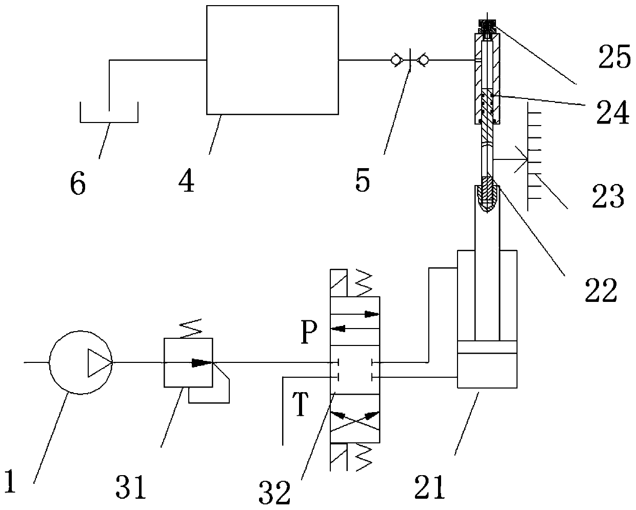
The invention relates to the technical field of leakage testing, and discloses a leakage testing device which comprises a pressurizing cylinder (21) and a pressure receiving cylinder (22) communicating with a tested valve (4), wherein a piston rod of the pressurizing cylinder (21) is connected with a moving rod of the pressure receiving cylinder (22) in series, so that the piston rod of the pressurizing cylinder (21) drives the moving rod of the pressure receiving cylinder (22) to move axially when moving axially, or the moving rod of the pressure receiving cylinder (22) drives the piston rodof the pressurizing cylinder (21) to axially move when moving axially. The leakage testing device of the invention has the beneficial effects that: the piston rod of the pressurizing cylinder and themoving rod of the pressure receiving cylinder are fixedly connected together, so that under the action of cooperation of the pressurizing cylinder and the pressure receiving cylinder, the piston rod of the pressurizing cylinder and the moving rod of the pressure receiving cylinder move axially at the same time, the leakage amount of the tested valve can be obtained according to the movement amountof the moving rod and the piston rod which are connected together, therefore, the leakage testing device is high in measuring precision, is capable of achieving continuous test, and is simple in structure and easy to implement.

Description

technical field [0001] The invention relates to the technical field of leak testing. Specifically, it relates to a leak testing device and a leak testing method. Background technique [0002] At present, the internal leakage test methods for hydraulic valves mainly include manual recording method; flow meter method: weighing method, pressure drop method, etc., when testing or using pressure oil before the tested valve, leakage through the valve core gap, in Measure the leakage at the T port; or add pressure oil before the tested valve, leak through the valve core gap, and measure the leakage at the inflow port. [0003] Some of the problems existing in the current test methods are poor measurement accuracy; some have long waiting time for stabilization and low efficiency; some require test instruments to withstand high pressure and high cost. Contents of the invention [0004] The purpose of the present invention is to provide a leak testing device to overcome the proble...

Claims


Application Information

Patent Timeline
Patent Type & Authority Applications(China)
IPC IPC(8): G01M3/28
CPCG01M3/2876
Inventor 李林岩
Owner ZOOMLION HEAVY IND CO LTD
Learn More