Ultraviolet testing machine

A testing machine and ultraviolet technology, applied in optical instrument testing, machine/structural component testing, measuring devices, etc., can solve the problems of inability to continuously perform, weak light intensity, and large energy, so as to improve the test effect and improve the accuracy. Effect

Pending Publication Date: 2018-09-04
XIAMEN SHIRUI OPTOELECTRONICS TECH CO LTD
View PDF6 Cites 0 Cited by
  • Summary
  • Abstract
  • Description
  • Claims
  • Application Information

AI Technical Summary

Problems solved by technology

However, since each LED lamp bead is a point light source, the light output intensity of the interval area between two adjacent LED lamp beads is relatively weak. Moreover, there is also a gap between the LED lamp beads and the edge of the lamp board, so the lamp The light intensity at the edge of the board is also weak
Therefore, the light intensity of different parts of the same lamp panel is not uniform, so it is necessary to test the intensity of the light output surface of the ultraviolet lamp. The existing test method is to use a hand-held ultraviolet detector This test method can only be tested point by point, and cannot be carried out continuously, and because the energy of the UV lamp is very large (especially for the lamp used for UV curing), in order to avoid causing harm to the detector during the test Injury, after a test, you need to wait for the UV lamp to cool down before proceeding to the next test

Method used


Image

  • Ultraviolet testing machine
  • Ultraviolet testing machine
  • Ultraviolet testing machine

Examples


Embodiment Construction

[0027] To further illustrate the various embodiments, the present invention is provided with drawings. These drawings are a part of the disclosure of the present invention, which are mainly used to illustrate the embodiments, and can cooperate with the related description in the specification to explain the operation principle of the embodiments. With reference to these contents, those of ordinary skill in the art should be able to understand other possible implementations and advantages of the present invention. The components in the figure are not drawn to scale, and similar component symbols are usually used to indicate similar components.

[0028] The present invention will now be further described with reference to the drawings and specific embodiments.

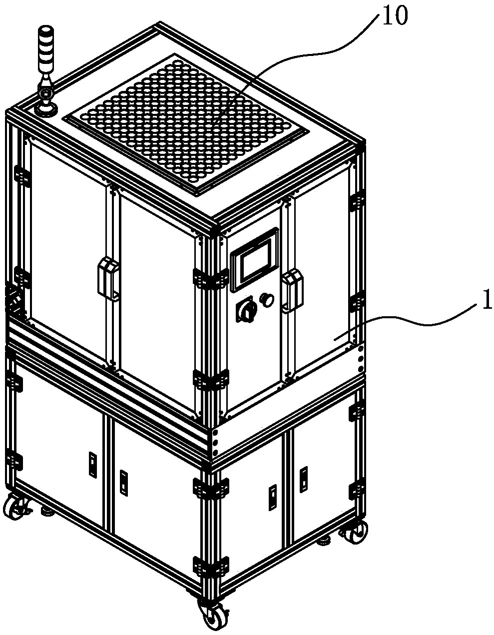
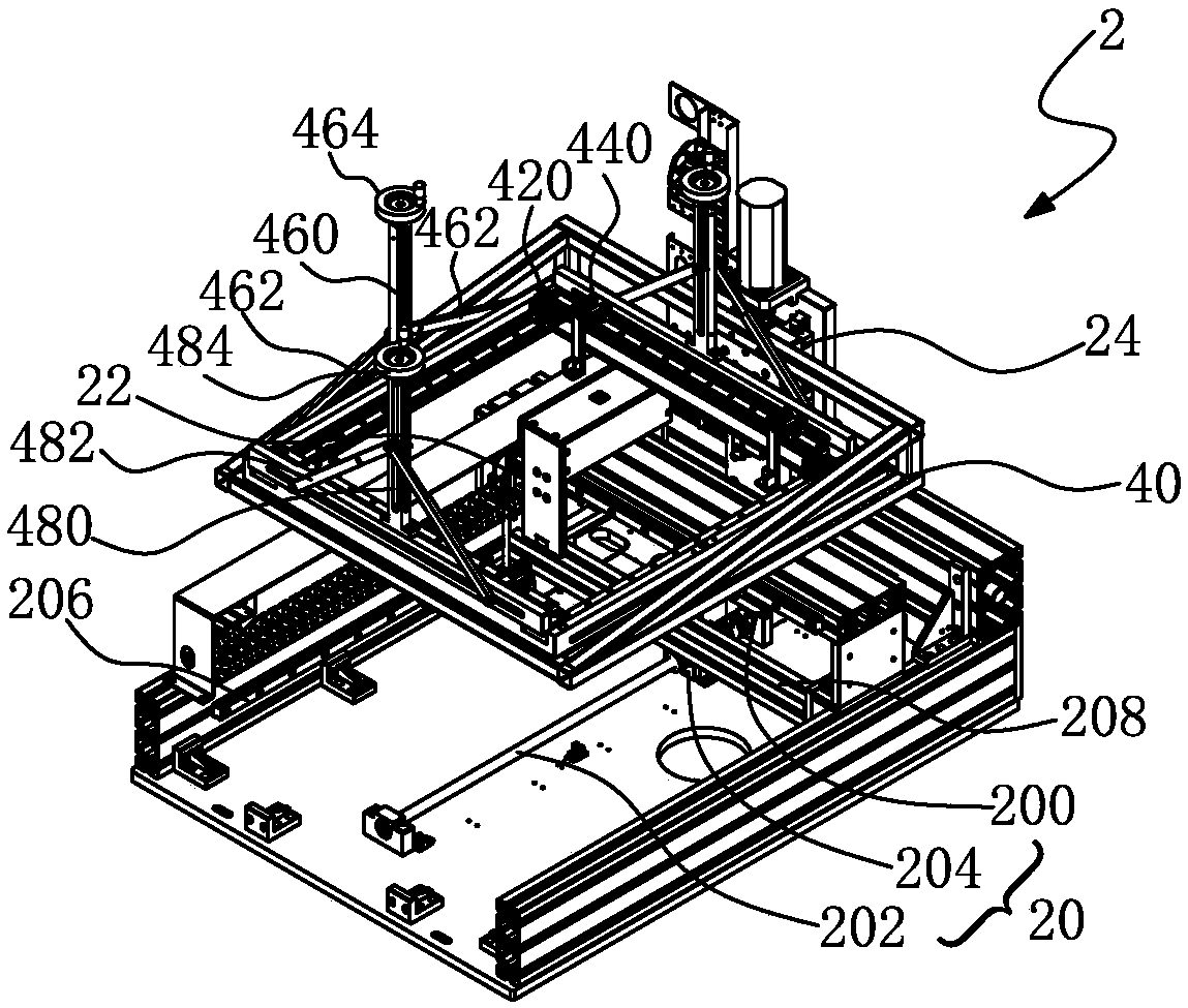
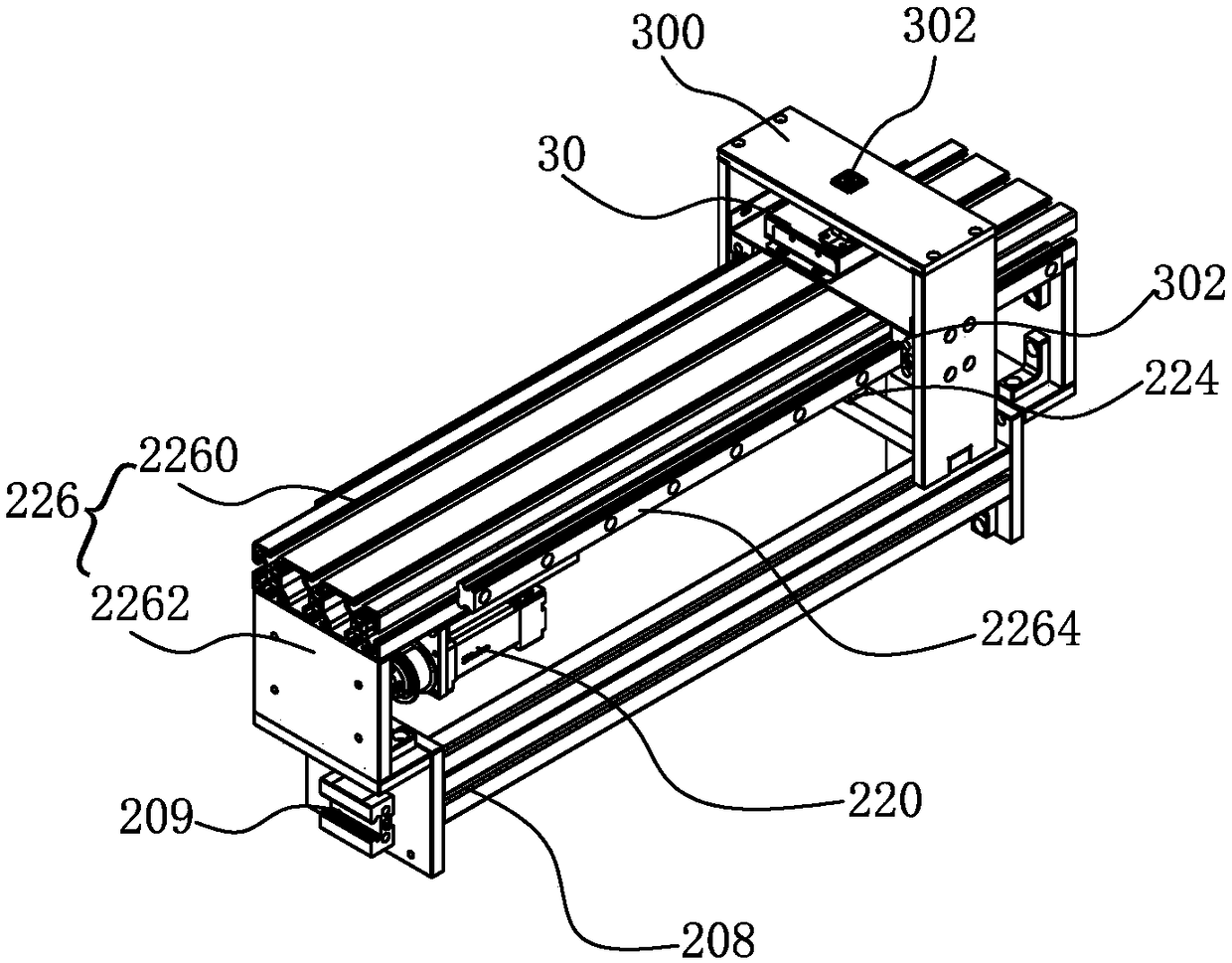
[0029] Such as Figure 1-Figure 6 As shown, the present invention provides an ultraviolet testing machine, which includes a machine frame 1 and a three-axis test device 2. The three-axis test device is installed on the machi...


PUM


Abstract

The invention relates to an ultraviolet testing machine comprising a bench frame and a three-axis testing device. The three-axis testing device installed on the bench frame consists of an x-axis translation assembly, a y-axis translation assembly and a z-axis translation assembly; an ultraviolet test probe is fixedly installed at a second sliding block of the y-axis translation assembly; and an ultraviolet lamp fixture is fixedly installed at a third sliding block of the z-axis translation assembly. Therefore, three-axis synchronous testing of the ultraviolet testing machine is realized.

Description

Technical field [0001] The invention relates to the field of UV testing equipment, in particular to an ultraviolet testing machine. Background technique [0002] Conventional UV curing lamps usually use mercury lamps as the UV light source. However, if discarded mercury lamps are not properly disposed of, it will cause environmental problems. In addition, the mercury lamp consumes a lot of power and generates a lot of waste heat during operation. Therefore, it needs to be used with a large high-voltage transformer and a heat dissipation mechanism, which makes it difficult to effectively reduce the volume of the UV curing lamp. In order to avoid the aforementioned shortcomings of mercury lamps, the industry has developed UV light-emitting diode curing lamps that use light-emitting diodes (LEDs) as UV light sources. [0003] The existing ultraviolet light emitting diode curing lamps are arranged with a plurality of LED lamp beads (LED units) spaced on a lamp panel. However, since e...

Claims


Application Information

Patent Timeline
Patent Type & Authority Applications(China)
IPC IPC(8): G01M11/00
CPCG01M11/00
Inventor 钟添荣林森阙方伟郭东栋符道永吴闯
Owner XIAMEN SHIRUI OPTOELECTRONICS TECH CO LTD
Why Eureka
Try Eureka