
Transformer fault diagnosis method based on vibration blind source separation and Bayesian model

A transformer fault and Bayesian model technology, applied in the field of power systems, can solve problems such as lack of faults, increased difficulty in diagnosis, difficulty in meeting the requirements for accuracy and fault location, etc.

Inactive Publication Date: 2020-01-17
CHONGQING UNIV
View PDF3 Cites 4 Cited by
  • Summary
  • Abstract
  • Description
  • Claims
  • Application Information

AI Technical Summary

Problems solved by technology

However, due to the lack of theoretical analysis and the lack of long-term online monitoring applications, there are still many bottlenecks in the actual daily work: first, the vibration signal monitored by the sensor is composed of the vibration signals of the transformer's internal winding and iron core. Its vibration spectrum is mostly in an overlapping state in the frequency domain of 100-2000 Hz. The vibration analysis method usually judges the internal fault of the transformer based on the vibration amplitude of 100 Hz. However, due to the aliasing of the vibration signals of the internal components of the transformer, it often leads to an increase in the difficulty of diagnosis and failure. The correct rate of diagnosis is not high; secondly, the main methods used in vibration analysis are wavelet analysis and empirical mode decomposition, but these two methods can only decompose vibration signals of different frequencies, and cannot The vibration signal is separated, and the location of the fault of the transformer cannot be accurately located to a specific component inside the transformer. It is necessary to check the status of the power failure to make a judgment, and the power failure inspection often has a great impact on the reliability of the power supply.
The traditional vibration analysis method is difficult to meet the current requirements for the accuracy and fault location of transformer internal fault diagnosis, and new methods must be introduced to improve it

Method used


Image

  • Transformer fault diagnosis method based on vibration blind source separation and Bayesian model
  • Transformer fault diagnosis method based on vibration blind source separation and Bayesian model
  • Transformer fault diagnosis method based on vibration blind source separation and Bayesian model

Examples


Embodiment Construction

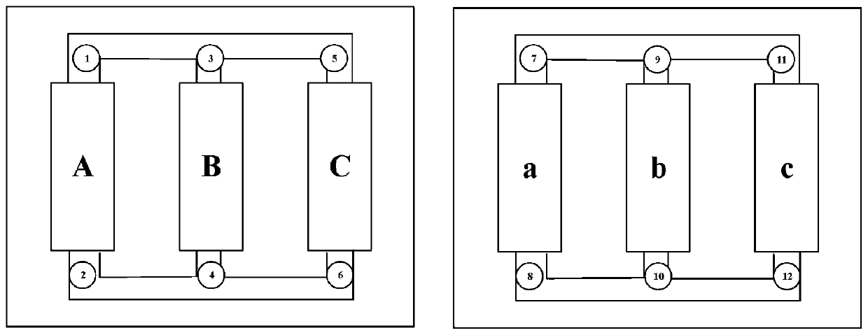
[0037] Embodiments of the present invention are described below through specific examples, and those skilled in the art can easily understand other advantages and effects of the present invention from the content disclosed in this specification. The present invention can also be implemented or applied through other different specific implementation modes, and various modifications or changes can be made to the details in this specification based on different viewpoints and applications without departing from the spirit of the present invention. It should be noted that the diagrams provided in the following embodiments are only schematically illustrating the basic concept of the present invention, and the following embodiments and the features in the embodiments can be combined with each other in the case of no conflict.

[0038] Wherein, the accompanying drawings are for illustrative purposes only, and represent only schematic diagrams, rather than physical drawings, and should...


PUM


Abstract

The invention relates to a transformer fault diagnosis method based on vibration blind source separation and a Bayesian model, and belongs to the field of power systems. The method comprises the stepsof: measuring a transformer vibration signal by using a vibration acceleration sensor, selecting a blind source separation algorithm for the basic method, performing signal separation on the measuredtransformer vibration signal by using the blind source separation technology to obtain a corresponding signal frequency spectrum of an internal component of a transformer, establishing a Bayesian network model based on the Bayesian network theory, importing a frequency ratio at 100Hz of the vibration signal as a fault feature vector into the Bayesian network model to serve as a root node, settingoperating state parameters of the transformer, respectively expressing the operating state parameters with different numerical values, and judging a fault state of the transformer according to the numerical value of the root node in a column vector of the root node.

Description

technical field [0001] The invention belongs to the field of power systems, and relates to a transformer fault diagnosis method based on vibration blind source separation and a Bayesian model. Background technique [0002] The commonly used detection measures for internal faults of transformers mainly include: short-circuit impedance method, frequency response analysis method, low-voltage pulse method, transfer function method, etc. However, these methods or experimental methods are complex and have high requirements for equipment status, or require the transformer to be out of operation, and it is difficult to meet the requirements of no time difference monitoring, or the monitoring results are hysteresis, and it is often difficult to detect latent faults as early as possible. Fault. In addition, most of these methods cannot locate the internal fault of the transformer, and can only be used to determine whether a fault occurs inside the transformer, which has relatively la...

Claims


Application Information

Patent Timeline
Patent Type & Authority Applications(China)
IPC IPC(8): G01R31/62G01H17/00G06K9/62G06N7/00
CPCG01H17/00G06N7/01G06F18/2134
Inventor 张占龙武雍烨邓军蒋培榆董子健
Owner CHONGQING UNIV
Learn More