An Imaging System Based on Quasi-Double Gaussian Structure
An imaging system, Gaussian technology, applied in the field of photoelectric detection, can solve problems such as low capability and difficulty in realizing high-altitude long-distance imaging, and achieve the effect of increasing the detectable distance, realizing high-altitude long-distance imaging, and high imaging quality
- Summary
- Abstract
- Description
- Claims
- Application Information
AI Technical Summary
Problems solved by technology
Method used
Image
Examples
Embodiment 1
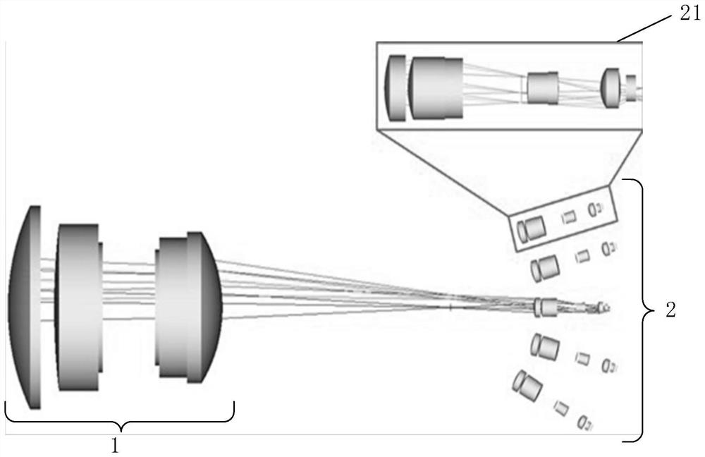
[0036] See figure 1 , figure 1 A schematic structural diagram of an imaging system based on a double-Gaussian structure provided by an embodiment of the present invention. The imaging system includes a primary imaging optical system 1 and a secondary imaging optical system 2 .
[0037]The main imaging optical system 1 includes a lens with a double-Gaussian structure, which is used to image the observation field of view on the spherical primary image surface, and correct the lateral chromatic aberration and astigmatism of the imaging during the imaging process, so that the position of each field of view on the spherical primary image surface image quality is similar. The similar image quality means that the aberration and distortion of each field of view position of the spherical primary image surface will not differ too much.
[0038] The quasi-double Gaussian structure lens described in this embodiment can be a lens combination with a double Gaussian structure, or a lens c...
Embodiment 2
[0042] On the basis of the first embodiment, this embodiment describes in detail the specific structure of the primary imaging optical system and the structure of the secondary imaging optical system.
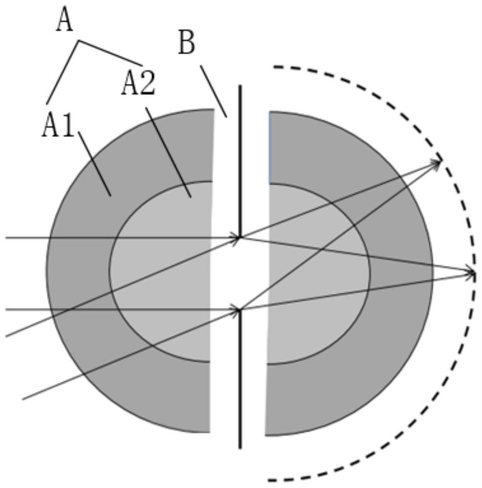
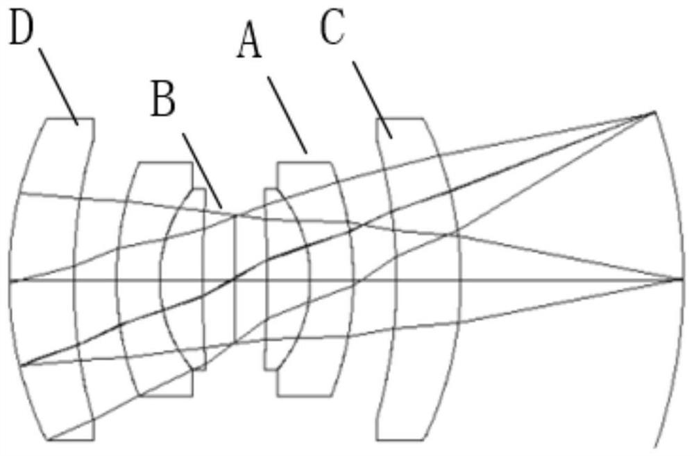
[0043] See Figure 2a-Figure 2c , Figure 2a-Figure 2c It is a schematic diagram of a design process of a main imaging optical system provided by an embodiment of the present invention. The main imaging optical system 1 is an important component structure of the wide-field-of-view high-resolution imaging system. Its design process is as follows: the first choice is to select a symmetrical single-center objective lens A1, and the single-center objective lens has a ball lens A2 containing the center of curvature to form a ball lens. structure A, then an air gap B is inserted between the split halves of this concentric spherical lens, see Figure 2a ; By introducing an air gap B, the radius of curvature of the system is optimized. Afterwards, lens element C is inserted between ...
Embodiment 3
[0064] On the basis of embodiment two, this embodiment adopts image 3 and Figure 4 The formed imaging system is optimized according to the following design requirements: the focal length of the system is 115mm, which meets the requirements of telephoto long-distance imaging (about 7km), the imaging instantaneous field of view is 36°×36°, and the detector is Sony IMX226. Pixel size 1.85μm×1.85μm, active pixel array 4000(H)×3000(V), effective photosensitive area 7.5mm(H)×5.55mm(V), about 12M pixels, frame rate 30fps; imaging band is visible light band.
[0065] After optimization, please refer to Table 1 for the structural parameters of the main imaging optical system 1 , and please refer to Table 2 for the structural parameters of each sub-secondary imaging optical system 21 .
[0066] Surf:Type Radius Thickness glass Semi-Diameter OBJ Infinity Infinity - Infinity 1 227.825 28.093 BSM93 108.187 2 525.343 26.459 103.430 3 ...
PUM
 Abstract
Description
Claims
Application Information
 - R&D
- Intellectual Property
- Life Sciences
- Materials
- Tech Scout
- Unparalleled Data Quality
- Higher Quality Content
- 60% Fewer Hallucinations
Browse by: Latest US Patents, China's latest patents, Technical Efficacy Thesaurus, Application Domain, Technology Topic, Popular Technical Reports.
© 2025 PatSnap. All rights reserved.Legal|Privacy policy|Modern Slavery Act Transparency Statement|Sitemap|About US| Contact US: help@patsnap.com


