Normally-closed reed switch

A reed switch, normally closed technology, applied in the field of reed switches, can solve the problems of easy to connect the normally open pins by mistake, failure of the reed switch, and inability to differ in magnetic field strength, etc.

Inactive Publication Date: 2020-01-17
珠海德信科电子有限公司
View PDF5 Cites 0 Cited by
  • Summary
  • Abstract
  • Description
  • Claims
  • Application Information

AI Technical Summary

Problems solved by technology

The disadvantage of this method is that the magnetic field strength of the two magnets cannot be much different. If the strength of the magnet used for triggering is much weaker than the attached magnet, the reed switch cannot be disconnected; if it is too strong, after disconnection, the trigger The magnet will re-magnetize the shrapnel in the reed switch, and the reed switch will be closed again; if the polarity direction of the magnet is wrong during use, it will not be possible to disconnect the reed switch
Moreover, the process of attaching a magnet to a reed switch requires professional equipment and is difficult
In addition, there is another way to use a switching reed switch, discarding the normally open pin and using only the normally closed pin as a normally closed reed switch. The disadvantage of this method is that the normally open and normally closed The closed pins are very close, and it is easy to mistakenly connect the normally open pins during the wiring process, causing the reed switch to fail
Therefore, these two methods are not convenient to use

Method used


Image

  • Normally-closed reed switch
  • Normally-closed reed switch
  • Normally-closed reed switch

Examples


Embodiment Construction

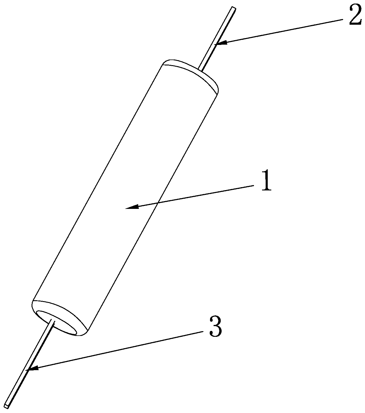
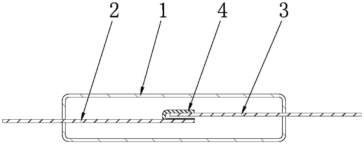
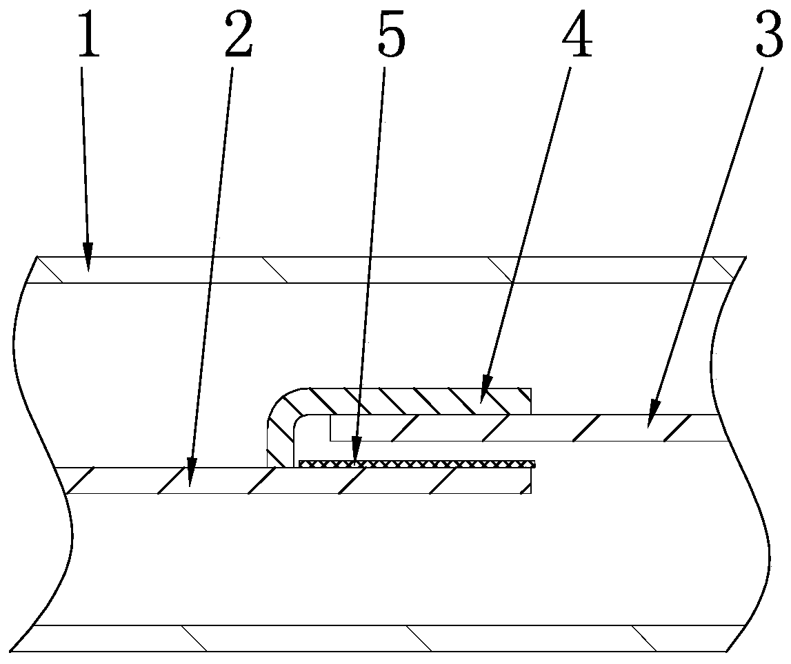
[0022] see Figure 1-Figure 4 , a kind of normally closed reed switch of the present invention comprises a tube body 1, and the tube body 1 is an insulating tube. In this embodiment, the tube body 1 is a glass tube; There are a first magnetically conductive shrapnel 2 and a second magnetically conductive shrapnel 3, one end of the first magnetically conductive shrapnel 2 and one end of the second magnetically conductive shrapnel 3 are sealed inside the tube body 1, and the tube body 1 is filled with The inert gas is used to protect the first magnetically conductive shrapnel 2 and the second magnetically conductive shrapnel 3 from being oxidized and corroded when arc sparks are generated when the circuit is turned on or off.

[0023] Further, the length direction of the first magnetic shrapnel 2 and the second magnetic shrapnel 3 are parallel to the length direction of the pipe body 1, and the first magnetic shrapnel 2 and the second magnetic shrapnel 3 are both electrically co...


PUM


Abstract

The invention relates to the technical field of reed switches, discloses a normally-closed reed switch that comprises a pipe body, a first magnetic conductive elastic sheet and a second magnetic conductive elastic sheet, wherein one end of the first magnetic conductive elastic sheet and one end of the second magnetic conductive elastic sheet are both located in the pipe body and overlapped with each other; a conductive bifurcated structure is arranged at one end of the first magnetic conductive elastic sheet, the second magnetic conductive elastic sheet is located between the first magnetic conductive elastic sheet and the conductive bifurcated structure, and an insulating layer is arranged between one end of the second magnetic conductive elastic sheet and one end of the first magnetic conductive elastic sheet. When the reed switch is not triggered, one end of the second magnetic conductive elastic sheet is in contact with the conductive bifurcated structure, and the reed switch is conducted; when the reed switch is triggered, under the action of an external magnetic field, one end of the second magnetic conductive elastic sheet is bent towards the first magnetic conductive elastic sheet, the second magnetic conductive elastic sheet is separated from the conductive bifurcated structure, and the insulating layer, the first magnetic conductive elastic sheet and the second magnetic conductive elastic sheet cannot be conducted after being attracted with one another, so that the second magnetic conductive elastic sheet and the first magnetic conductive elastic sheet are changedinto a disconnected state from a conducted state. The reed switch is simple in structure and convenient to use.

Description

technical field [0001] The invention relates to the technical field of dry reed switches, in particular to a normally closed dry reed switch. Background technique [0002] At present, the existing normally closed reed switch mostly adopts a magnet attached to a normally open reed switch to keep the reed switch closed. When in use, a magnet with opposite polarity is used to trigger the reed switch to disconnect the reed switch. The disadvantage of this method is that the magnetic field strength of the two magnets cannot be much different. If the strength of the magnet used for triggering is much weaker than the attached magnet, the reed switch cannot be disconnected; if it is too strong, after disconnection, the trigger The magnet will re-magnetize the shrapnel in the reed switch, and the reed switch will be closed again; if the polarity direction of the magnet is wrong during use, it will not be possible to disconnect the reed switch. Moreover, the process of attaching a ma...

Claims


Application Information

Patent Timeline
IPC IPC(8): H01H36/00
CPCH01H36/008
Inventor 黄宗华董建华
Owner 珠海德信科电子有限公司
Why Eureka
Try Eureka