
Microphone calibration method and microphone packaging structure

A calibration method and microphone technology, applied in frequency/direction characteristic devices, sensor components, microphone mouth/microphone accessories, etc., can solve the problems of occupying internal space, different appearance of microphones, and inability to remove lead wires, etc., to achieve structural small effect

Active Publication Date: 2020-01-17
WEIFANG GOERTEK MICROELECTRONICS CO LTD
View PDF6 Cites 0 Cited by
  • Summary
  • Abstract
  • Description
  • Claims
  • Application Information

AI Technical Summary

Problems solved by technology

[0002] In the traditional microphone packaging structure, in order to realize the parameter calibration of the microphone, it is necessary to add a standard lead on the chip, but after the parameter calibration is completed, this lead is no longer needed, but since this lead is fixed on the chip, it is not necessary This lead cannot be removed, which not only occupies the internal space, but also makes the appearance of the microphone different from other microphones that do not require parameter calibration

Method used


Image

  • Microphone calibration method and microphone packaging structure
  • Microphone calibration method and microphone packaging structure
  • Microphone calibration method and microphone packaging structure

Examples


Embodiment Construction

[0028] Various exemplary embodiments of the present invention will now be described in detail with reference to the accompanying drawings. It should be noted that the relative arrangements of components and steps, numerical expressions and numerical values ​​set forth in these embodiments do not limit the scope of the present invention unless specifically stated otherwise.

[0029] The following description of at least one exemplary embodiment is merely illustrative in nature and in no way taken as limiting the invention, its application or uses.

[0030] Techniques, methods and devices known to those of ordinary skill in the relevant art may not be discussed in detail, but where appropriate, such techniques, methods and devices should be considered part of the description.

[0031] In all examples shown and discussed herein, any specific values ​​should be construed as exemplary only, and not as limitations. Therefore, other instances of the exemplary embodiment may have dif...


PUM


Abstract

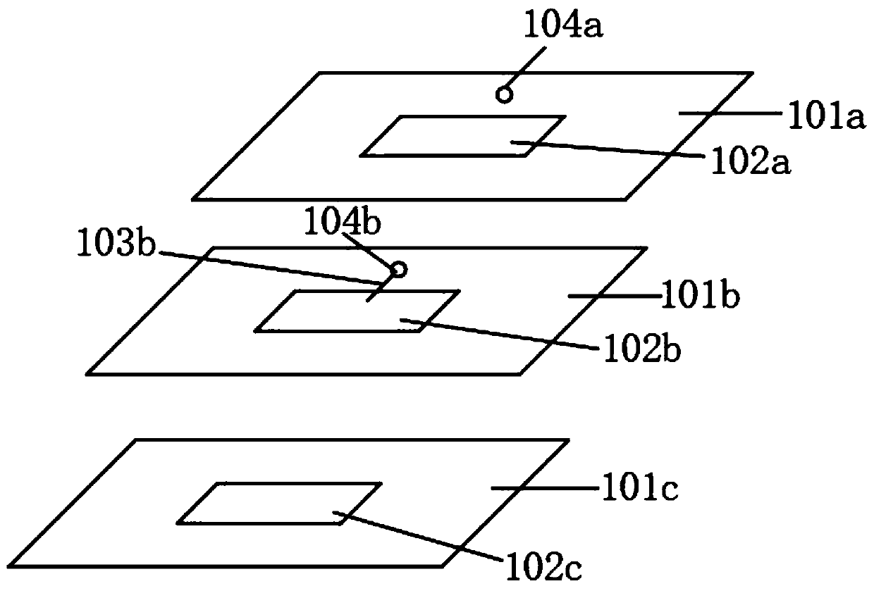
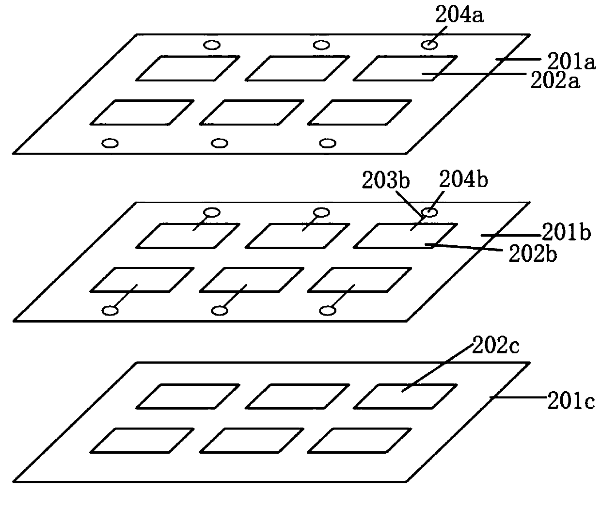
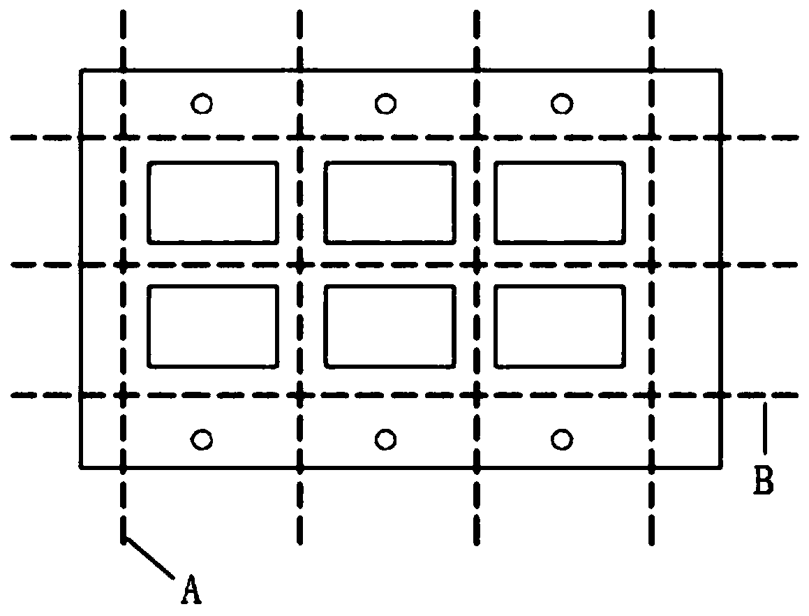
The invention discloses a microphone calibration method and a microphone packaging structure. The method comprises the following steps: providing a PCB which comprises a surface layer, at least one inner layer, and a bottom layer; wherein the surface layer is provided with at least one placement area, and each placement area is correspondingly provided with a first conductive point; at least one inner layer is provided with a lead, one end of the lead is electrically connected with a first conductive point, and the other end of the lead is electrically connected with the placement area; enabling the microphone to be tested to be electrically connected with the lead; connecting a microphone detection circuit to the first conductive point, and performing calibration detection on the microphone to be detected; and after the calibration detection is completed, cutting off a local structure with the first conductive point and at least one part of the lead on the PCB. According to the invention, the lead connected with the external circuit is arranged on the inner layer of the PCB, and after the parameter calibration of the microphone is completed, the first conductive point and at leastone part of the local structure of the lead are cut off, so that the structure of the microphone is lighter and smaller.

Description

technical field [0001] The present invention relates to the technical field of acoustic-electric conversion, in particular to a microphone calibration method and a microphone package structure. Background technique [0002] In the traditional microphone packaging structure, in order to realize the parameter calibration of the microphone, it is necessary to add a standard lead on the chip, but after the parameter calibration is completed, this lead is no longer needed, but since this lead is fixed on the chip, it is not necessary It is not possible to remove this lead, which not only takes up internal space, but also makes the appearance of the microphone different from other microphones that do not require parametric calibration. [0003] In order not to affect the appearance of the microphone, the invention provides a method for calibrating the microphone and the microphone array and the microphone. Contents of the invention [0004] An object of the present invention is...

Claims


Application Information

Patent Timeline
Patent Type & Authority Applications(China)
IPC IPC(8): H04R1/08H04R1/32H04R29/00
CPCH04R1/08H04R1/326H04R29/004
Inventor 马路聪党茂强
Owner WEIFANG GOERTEK MICROELECTRONICS CO LTD
Learn More