Power output circuit, LED drive circuit, drive method and LED

A technology of LED drive and power output, applied in the field of electronics, can solve problems such as increased cost, poor power consistency, design limitations, etc., to achieve the effect of solving interference, high reliability, and good consistency

Pending Publication Date: 2020-01-17
UP SHINE LIGHTING CO
View PDF0 Cites 0 Cited by
  • Summary
  • Abstract
  • Description
  • Claims
  • Application Information

AI Technical Summary

Problems solved by technology

[0003] (1) Thyristor dimming type dimming drive: For traditional buildings, a large number of thyristor dimmers are installed. The choice of most people, but for the developer, this operation adds a large number of dimming circuits, which can maintain the dummy load of the SCR conduction, which greatly increases the cost and reduces the work efficiency, while for the user For example, the dimming effect used may be difficult to achieve the ideal dimming effect due to different dimmers. For commercial lighting places, it is only necessary to achieve a specific brightness, and it is impossible to maintain a consistent brightness requirement.
[0004] (2) 0-10V, PMW, DALI and other intelligent dimming drivers: this type of implementation must be implemented with a dedicated IC with a dimming port and a dedicated dimming device, and the cost is relatively high
[0005] (3) Dial code to adjust the power drive power supply: Usually this circuit has two implementation methods, using a driver IC with an analog dimming port, through the code dialing method, different resistor voltage dividers are generated to realize the power adjustable function. This implementation must use a dedicated control IC with analog dimming pins, and the design is also limited to a certain extent.
The second implementation method is to adjust the power by connecting a resistor in parallel to the IC sampling pin, but the IC sampling pin usually only has a voltage of a few tenths of a volt, which is susceptible to interference, and the internal resistance of a mechanical switch such as a dial switch varies greatly. , making the consistency of the power poor

Method used


Image

  • Power output circuit, LED drive circuit, drive method and LED
  • Power output circuit, LED drive circuit, drive method and LED
  • Power output circuit, LED drive circuit, drive method and LED

Examples


Embodiment 1

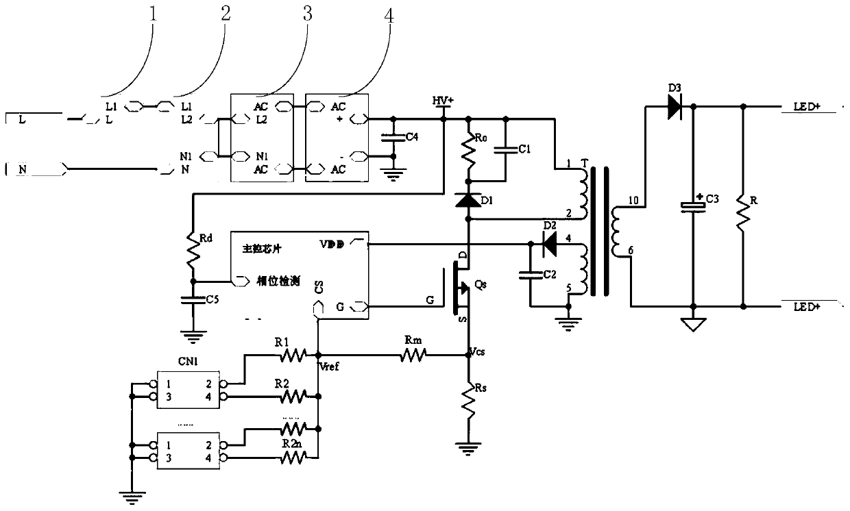
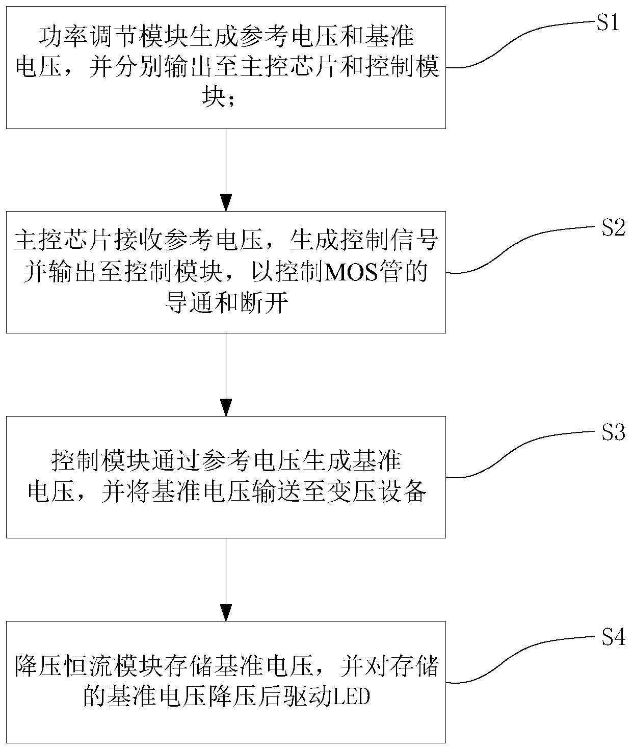
[0035] refer to figure 1 , Embodiment 1 provides a power output circuit, the power output circuit includes a main control chip, a power adjustment module and a control module.

[0036] In a specific embodiment, the first port of the main control chip is connected to the power adjustment module, and the second port of the main control chip is connected to the control module; the frequency adjustment module is used to generate the reference voltage V ref and reference voltage V cs , where the reference voltage V ref Output to the main control chip through the first port, the reference voltage V cs Output to the control module; the main control chip is used to receive the reference voltage V of the power regulation module ref , generate the control model and output it to the control module; the control module is used to pass the reference voltage V ref Generates the reference voltage V cs , and set the reference voltage V cs sent to the transformer equipment. In this embod...

Embodiment 2

[0043] read on figure 1 , embodiment 2 provides an LED drive circuit, the LED lamp drive circuit includes the power output circuit of embodiment 1, and also includes a step-down constant current module, the step-down constant current module is used to store the reference voltage V cs , and send it to the LED lamp after stepping down.

[0044] In a specific embodiment, the step-down constant current module includes a transformer T, a third diode D3, a third capacitor C3, and a discharge resistor; one end of the secondary coil of the transformer T is connected to the anode of the third diode D3, and the secondary The two ends of the coil are sequentially connected with the third capacitor C3 and the discharge resistor, and the two ends of the discharge resistor are respectively connected to the positive input terminal and the negative input terminal of the LED. The transformer T is an isolation transformer, which has a first primary winding, a second primary winding and a second...

Embodiment 3

[0063] Embodiment 3 is provided on the basis of Embodiment 2, and Embodiment 2 also provides an LED lamp driving circuit, the LED lamp driving circuit also includes a dimmer 1, a lightning protection unit 2, an EMI filter unit 3 and a rectification unit 4 ; The dimmer 1, the lightning protection unit 2, the EMI filter unit 3 and the rectification unit are sequentially connected to 4, and the fourth capacitor C4 is connected in parallel between the positive output terminal and the negative output terminal of the rectification unit and grounded.

[0064] The lightning protection unit 2, the EMI filter unit 3 and the rectification unit 4 combine with the main control chip to form a flyback circuit (buckboost circuit), which provides a stable constant current output for the LED light source, wherein: the lightning protection unit 2 is used to absorb the surge generated by the mains terminal The lightning surge signal is reduced to the range that the subsequent circuit can withstand...


PUM


Abstract

The invention relates to a power output circuit, an LED drive circuit, a drive method and an LED, wherein the power output circuit comprises a main control chip, a power adjustment module and a control module. According to the invention, a dialer is combined with a grounding resistor, so that the segmented dial-up power adjustment is realized; the dialer is connected with different grounding resistors and upper bias resistors for voltage division, so that different output currents are realized, and the purpose of multiple gear power is achieved; power adjustment is realized through a mode, andthe circuit output current is only related to the ratio of the grounding resistor to the upper bias resistor, so that the grounding resistor and the upper bias resistor can adopt the K-ohm resistors,the interference generated by the dialer or the line internal resistance is solved, the constant output currents with different magnitudes can be stably and accurately outputted, the cost is low, andthe reliability is high.

Description

technical field [0001] The invention relates to the field of electronic technology, in particular to a power output circuit, an LED driving circuit, a driving method and an LED. Background technique [0002] With the rapid development of LED lighting technology, various lighting products continue to emerge. In today's resource-scarce environment, people's awareness of energy conservation continues to strengthen. Usually, one type of lighting is used in different environments, and corresponding needs Meet different brightness requirements, for example, a 1.2-meter LED tube may have different power requirements such as 22W, 20W, 18W, 16W, etc., and a 3-inch downlight may also have 12W, 10W, 9W, 8W, 7W, 6W, 5W For so many cumbersome power requirements, the current adjustable power LED driver has the following disadvantages: [0003] (1) Thyristor dimming type dimming drive: For traditional buildings, a large number of thyristor dimmers are installed. The choice of most people...

Claims


Application Information

Patent Timeline
Patent Type & Authority Applications(China)
IPC IPC(8): H05B33/08H05B44/00
Inventor 成海斌谢祖华苏宗才李玉林
Owner UP SHINE LIGHTING CO
Why Eureka
Try Eureka