
Position adjusting mechanism of rigid ion source in cyclotron and adjusting method thereof

A technology of cyclotron and adjustment mechanism, which is applied to magnetic resonance accelerators, accelerators, electrical components, etc., can solve the problems of long time consumption, travel limitation of displacement, and small accelerator space.

Pending Publication Date: 2020-01-17
INST OF FLUID PHYSICS CHINA ACAD OF ENG PHYSICS
View PDF0 Cites 2 Cited by
  • Summary
  • Abstract
  • Description
  • Claims
  • Application Information

AI Technical Summary

Problems solved by technology

[0006] The technical problem to be solved by the present invention is that the existing flexible ion source is located inside the accelerator, it takes a long time to disassemble it, and at the same time, the radiation hazard is large, and the inner space of the accelerator is narrow, so that the adjustment range is small, and the displacement stroke is also limited, which is not convenient for a large range. Adjustment, so that the adjustment accuracy is low, thereby providing a position adjustment mechanism and its adjustment method of the rigid ion source in the cyclotron, the adjustment mechanism and its adjustment method are combined with the rigid ion source and installed outside the accelerator to ensure the accuracy of its displacement It is installed and fixed outside the vacuum, so that it can be disassembled quickly without being limited by the state of the accelerator. The volume size of the adjustment mechanism is not limited by the internal space of the accelerator, which can realize complex and precise multi-dimensional motion control.

Method used


Image

  • Position adjusting mechanism of rigid ion source in cyclotron and adjusting method thereof
  • Position adjusting mechanism of rigid ion source in cyclotron and adjusting method thereof
  • Position adjusting mechanism of rigid ion source in cyclotron and adjusting method thereof

Examples


Embodiment

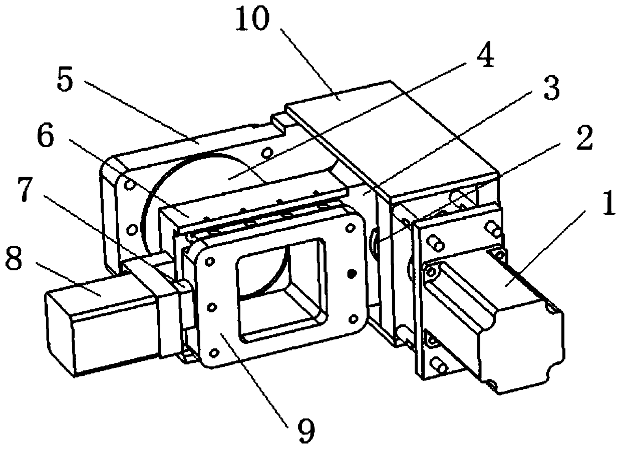
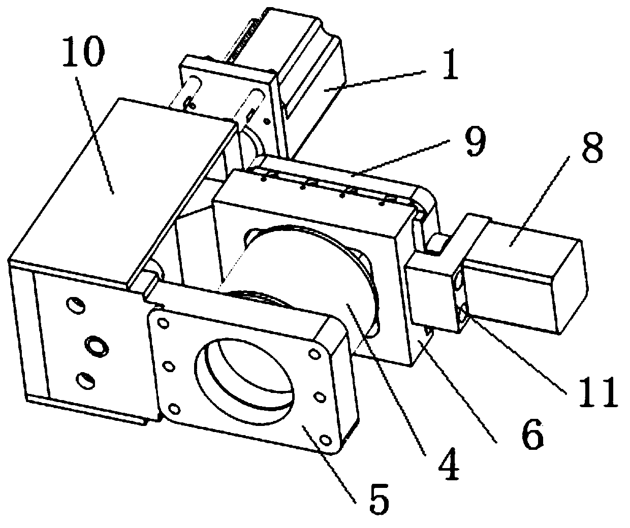
[0032] Such as figure 1 and figure 2 As shown, it is specially used for the position adjustment mechanism of the rigid ion source in the cyclotron. The cyclotron refers to the cyclotron using the internal ion source, and the ion beam is generated inside the accelerator. A support frame 10 with a hollow interior and openings on both sides is adopted, and a drive device-1 is installed on the outside of the support frame 10. The drive device-1 adopts a motor, and a guide rail-3 is arranged in the cavity of the support frame 10, and the drive device-1 and The connection of guide rail one 3 is realized by transmission device one 2, and transmission device one 2 is preferably lead screw one, and one end of lead screw one is connected with driving device one 1, and the other end passes through guide rail one 3, and the lead screw one is covered with a bearing After being inserted in the support frame 10, the leading screw can rotate around its own axis when the driving device 1 dri...


PUM


Abstract

The invention discloses a position adjusting mechanism of a rigid ion source in a cyclotron, which is characterized in that a guide rail I is arranged in a support frame, a driving device I is arranged outside the support frame, the driving device I is connected with a transmission device I, and the transmission device I is connected with the guide rail I; a first flange used for being fixed to anaccelerator shell is fixed to the supporting frame, a second guide rail is connected to the first guide rail, a second flange and a second driving device are arranged on the second guide rail, the second driving device is connected with a second transmission device, the second transmission device is connected with the second flange, and the moving direction of the second flange is perpendicular to the moving direction of the first guide rail. The mechanism is installed outside the vacuum, the size of the device is not limited by the internal space of the accelerator, and complex and accuratemulti-dimensional motion control can be achieved. And the bearing, the lead screw and the guide rail are not limited by oil any more when being lubricated. A transmission mechanism, a driving motor, asignal line, a power line and the like are all arranged outside the accelerator, and model selection and design are not limited by vacuum conditions any more.

Description

technical field [0001] The invention relates to the technical field of a cyclotron, in particular to a position adjustment mechanism and an adjustment method for a rigid ion source in a cyclotron. Background technique [0002] When a cyclotron accelerates charged particles, its charged particle beam has an external generation type and an internal generation type, that is, an external ion source and an internal ion source. Compared with the external ion source, the overall structure of the cyclotron using the internal ion source is more compact, the equipment structure is relatively simple, and the manufacturing cost and maintenance cost are much lower than the external ion source. [0003] The internal ion source needs regular maintenance and disassembly, and its relative position is not easy to fix. The accelerator is extremely sensitive to the position of the internal ion source, and a corresponding position adjustment mechanism is usually required for online adjustment. ...

Claims


Application Information

Patent Timeline
IPC IPC(8): H05H7/00H05H7/08H05H13/00
CPCH05H7/00H05H7/08H05H13/005H05H2007/082
Inventor 赵良超何小中马超凡龙全红杨兴林李洪
Owner INST OF FLUID PHYSICS CHINA ACAD OF ENG PHYSICS
Learn More