Down the hole drilling machine and method for drilling rock

A down-the-hole drilling rig and drill bit technology, which is applied in the field of fluid transportation and rock drilling, can solve problems such as unsatisfactory impact device efficiency, and achieve the effect of durable structure, strong structure, and improved efficiency

Active Publication Date: 2020-01-17
SANDVIK INTELLECTUAL PROPERTY AB
View PDF7 Cites 0 Cited by
  • Summary
  • Abstract
  • Description
  • Claims
  • Application Information

AI Technical Summary

Problems solved by technology

[0005] In known DTH rigs, the efficiency of the percussion device showed unsatisfactory

Method used


Image

  • Down the hole drilling machine and method for drilling rock
  • Down the hole drilling machine and method for drilling rock
  • Down the hole drilling machine and method for drilling rock

Examples


Embodiment Construction

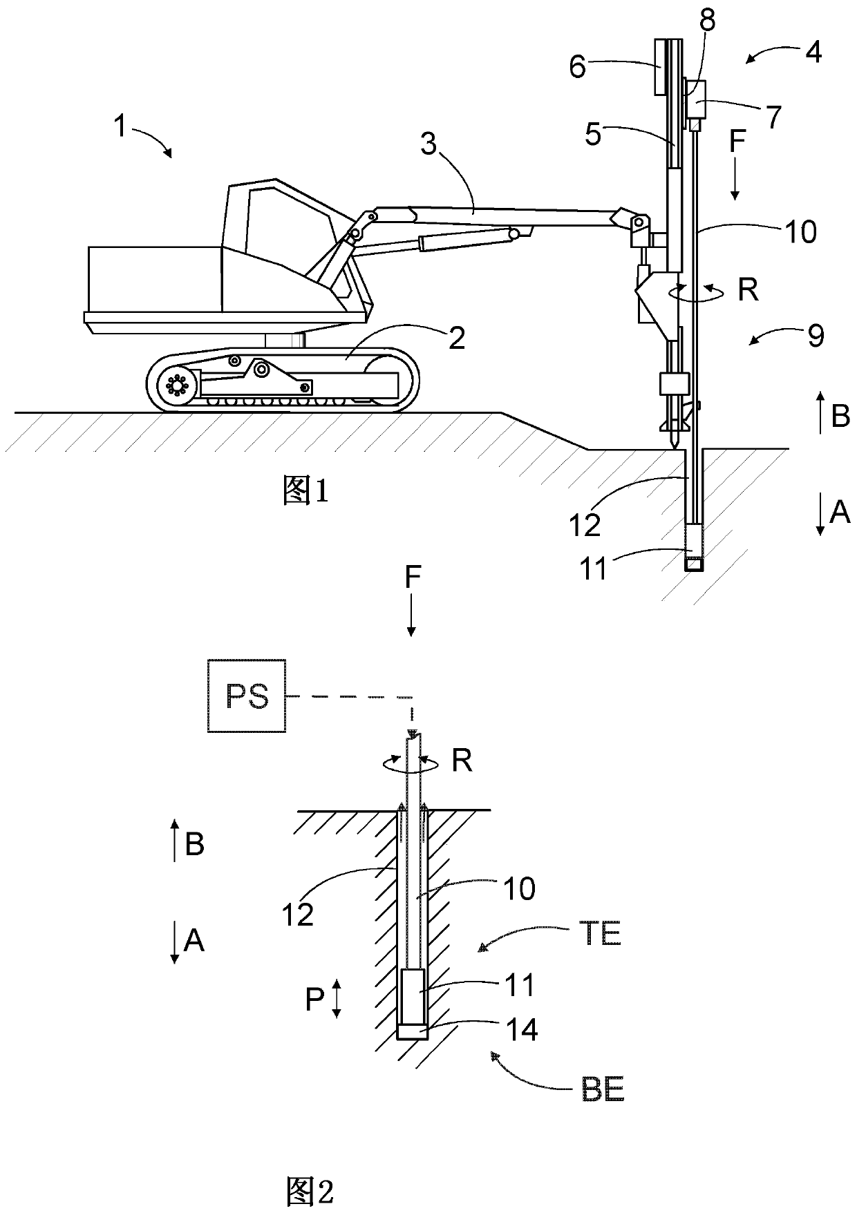
[0041] figure 1 A rock drilling machine 1 is shown comprising a movable carriage 2 provided with a drilling boom 3 . The drill boom 3 is provided with a rock drilling unit 4 comprising a feed beam 5 , a feed device 6 and a swivel unit 7 . The rotary unit 7 may comprise a gear system and one or more rotary motors. The swivel unit 7 may be supported to a carriage 8 with which it is movably supported to the feed beam 5 . The rotary unit 7 may be provided with a drilling rig 9 which may comprise one or more drilling pipes 10 and a DTH drilling rig 11 which are connected to each other and which are located in the drilling rig. 9 at the outermost end. During drilling, the DTH drill rig 11 is located in the borehole 12 .

[0042] figure 2 A DTH drilling rig 11 is shown comprising a percussion device 13 . The percussion device 13 is located at the opposite end of the drilling rig 9 with respect to the rotary unit 7 . During drilling, the drill bit 14 is directly connected to t...


PUM


Abstract

A down the hole rock drilling machine and a method of drilling rock. The drilling machine comprises a reciprocating piston (19), which has sleeve-like configuration. Inside a central opening (20) of the piston is arranged one or more fluid passages for conveying pressurized fluid during work cycle of an impact device of the drill machine.

Description

technical field [0001] The present invention relates to a down-the-hole drilling rig comprising a percussion device and in particular to fluid delivery within the percussion device. The drilling rig is provided with a reciprocating percussion piston moved by controlled feeding and discharging of pressurized fluid into and out of the working chamber, the working surface of which piston is located at the working chamber. The piston is configured to strike a drill bit directly connected to the drilling machine. [0002] Furthermore, the invention relates to a method for drilling rock. [0003] The technical field of the invention is described in more detail in the preambles of the independent claims of the present application. Background technique [0004] Able to drill holes in rocks with various rock drilling machines. Drilling can be performed using a method combining impact and rotation. Then, this kind of drilling is called percussion drilling. Furthermore, percussion...

Claims


Application Information

Patent Timeline
Patent Type & Authority Applications(China)
IPC IPC(8): E21B4/14
CPCE21B4/14E21B7/02E21B21/10E21B1/30E21B1/38E21B1/12E21B1/24
Inventor 奥利维耶·布吕昂代
Owner SANDVIK INTELLECTUAL PROPERTY AB
Why Eureka
Try Eureka