Patella driver

A technology of an insulator and a patella, applied in the field of medical devices, can solve the problems of general fixation effect, complicated operation, inability to select a patella prosthesis, etc., and achieves the effects of eliminating the holding posture, high implantation precision, and high clamping precision.

Active Publication Date: 2020-01-21
天衍医疗器材有限公司
View PDF23 Cites 3 Cited by
  • Summary
  • Abstract
  • Description
  • Claims
  • Application Information

AI Technical Summary

Problems solved by technology

[0003] The angle of the patella pressurizing block of the existing patella implanter cannot be adjusted. When pressing the patella prosthesis, the instrument needs to be tilted downward or upward at a certain angle. The operator's hand needs to maintain this state for a long time, causing discomfort, and Because the strength of the hand cannot be accurately grasped, it will affect the accuracy of the patella implantation; the operation of the existing patella driver locking at a certain angle is complicated, which increases the difficulty of the operation; the existing patella driver can only rely on Replacement of different types of drill guide blocks, unable to fine-tune to the appropriate drilling position according to the size of the patella, unable to select a suitable force point for the patella prosthesis, and the fixation effect is mediocre

Method used


Image

  • Patella driver
  • Patella driver
  • Patella driver

Examples


Embodiment Construction

[0026] The following will clearly and completely describe the technical solutions in the embodiments of the present invention with reference to the accompanying drawings in the embodiments of the present invention. Obviously, the described embodiments are only some, not all, embodiments of the present invention. Based on the embodiments of the present invention, all other embodiments obtained by persons of ordinary skill in the art without making creative efforts belong to the protection scope of the present invention.

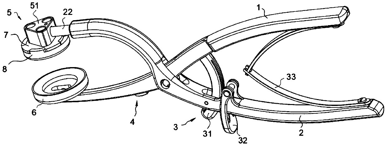
[0027] see figure 1 , the present invention provides a technical solution: a patella driver, including a first handle body 1 and a second handle body 2 hinged to each other, a locking device 3 is arranged between the first handle body 1 and the second handle body 2, One end of the second handle body 2 is hinged with a patella pressurizing block 6, and one end of the second handle body 2 is connected with a mounting portion 22, and one side of the mounting port...


PUM


Abstract

The invention discloses a patella driver. The patella driver comprises a first handle body and a second handle body hinged to each other, and a locking device is arranged between the first handle bodyand the second handle body; a patella pressing block is hinged to one end of the second handle body, installation parts are connected to one end of the second handle body, drill guide devices are arranged on one sides of the installation parts, patella end surface touch blocks are connected to the bottoms of the drill guide devices, and cambered surface clamping blocks are arranged at the bottomsof the patella end surface touch blocks; a direction adjusting device is arranged on the first handle body, and the direction adjusting device comprises a pushing block; and a sliding groove is formed in the first handle body, a slipping strip is slidably installed in the sliding groove, a rack is arranged on one side of the slipping strip, the installation parts are correspondingly arranged at the bottom of the patella pressing block, and a rotating shaft is rotatably connected between the two installation parts in an inserting mode. The patella driver has the characteristics of simple operation and being adapt to different implanting angles.

Description

technical field [0001] The invention relates to the technical field of medical devices, in particular to a patella driver. Background technique [0002] Knee replacement is a well-established bone and joint surgery in which the patient's joint is replaced with a joint prosthesis. Knee joint prosthesis includes femoral condyle, tibial plateau, tibial spacer, patella, extension rod, etc. The patella driver of the present invention is a surgical instrument for replacing the patella prosthesis, which integrates measurement, positioning and implantation. [0003] The angle of the patella pressurizing block of the existing patella implanter cannot be adjusted. When pressing the patella prosthesis, the instrument needs to be tilted downward or upward at a certain angle. The operator's hand needs to maintain this state for a long time, causing discomfort, and Because the strength of the hand cannot be accurately grasped, it will affect the accuracy of the patella implantation; the...

Claims


Application Information

Patent Timeline
Patent Type & Authority Applications(China)
IPC IPC(8): A61F2/46
CPCA61F2/461A61F2002/4687
Inventor 陆玲玲王健
Owner 天衍医疗器材有限公司
Why Eureka
Try Eureka