
Hydrodynamic linkage scouring and desilting facility

A technology of hydropower and facilities, applied in water conservancy projects, artificial waterways, buildings, etc., can solve the problems that silt and sand cannot be smoothly removed and affect the normal operation of the project

Inactive Publication Date: 2020-01-21
陈小娟
View PDF6 Cites 4 Cited by
  • Summary
  • Abstract
  • Description
  • Claims
  • Application Information

AI Technical Summary

Problems solved by technology

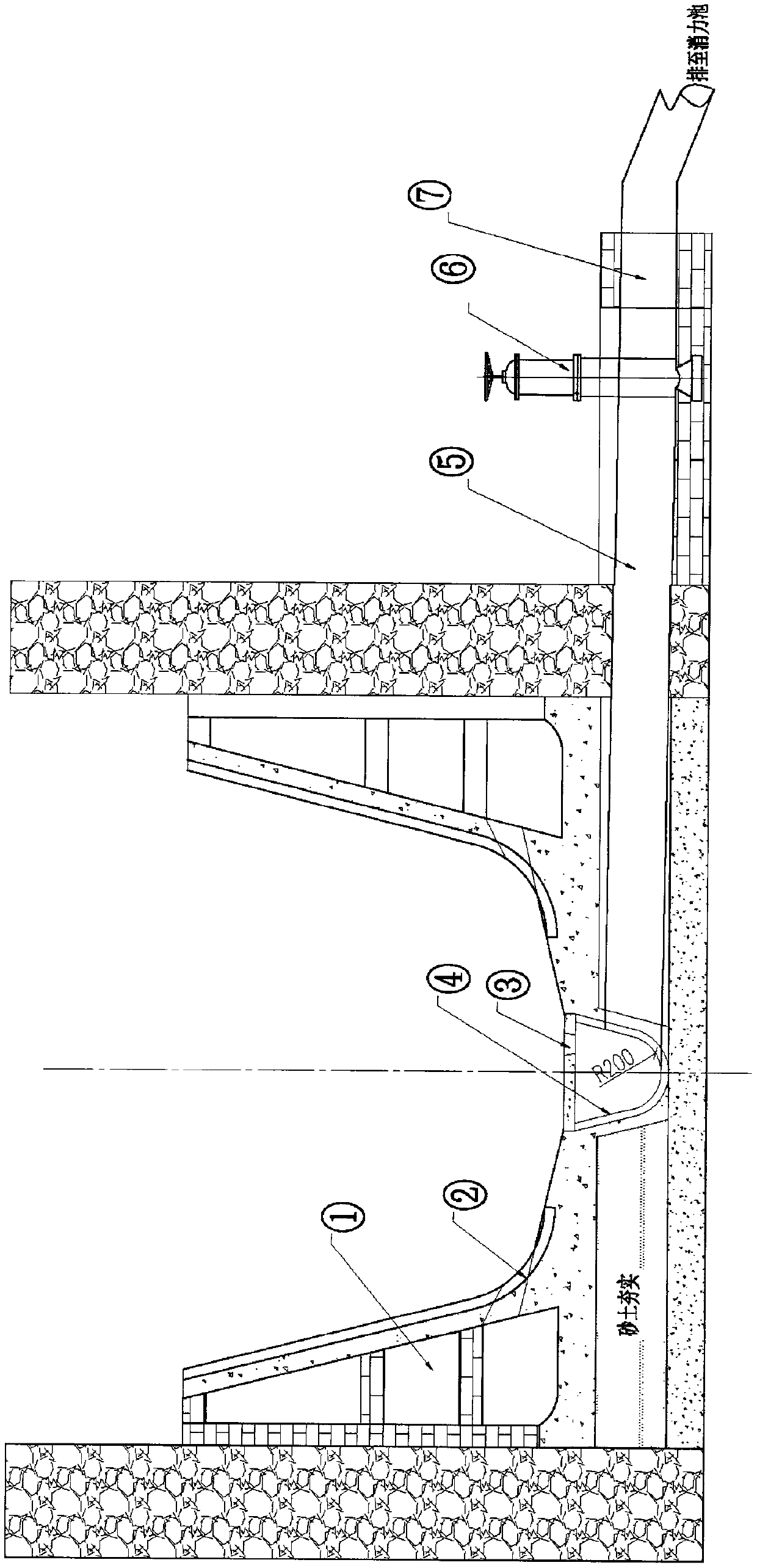
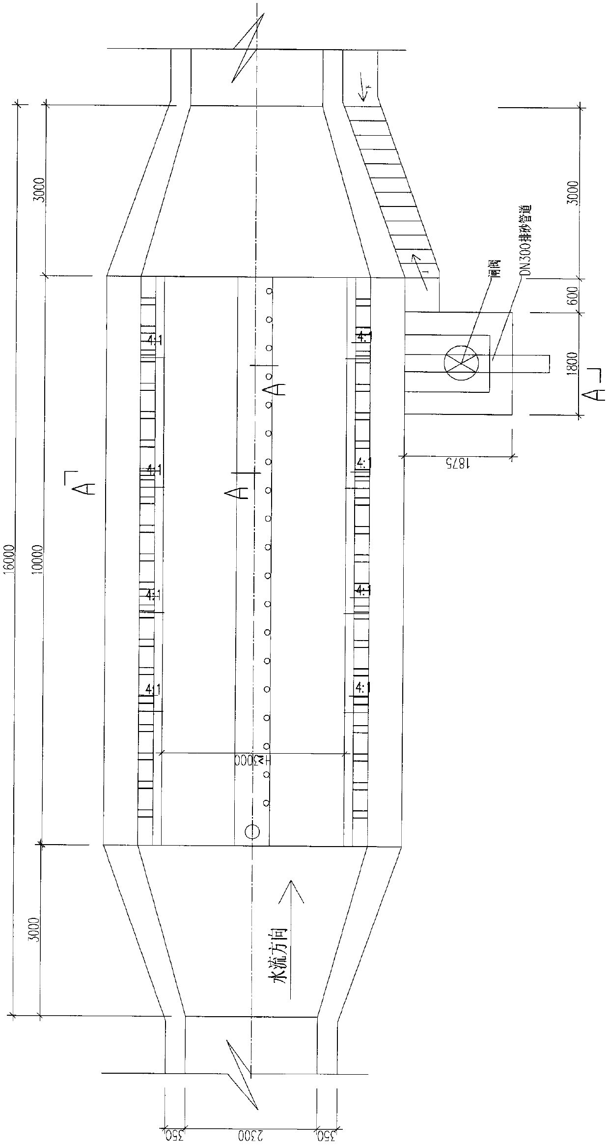
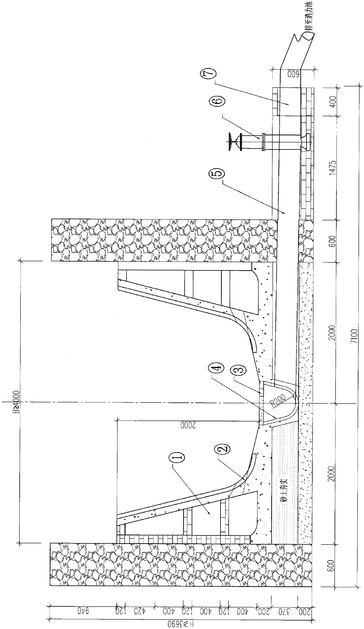
[0004] In order to change the water flow conditions that make it difficult to form silt and sand discharge at the bottom of the grit chamber, so that the silt and sand in the grit chamber cannot be smoothly removed and affect the normal operation of the project, this facility is located on the grit chamber through some engineering measures. The cluster jet formed by the half-U-shaped side wall of the water tank and the orifice at the bottom can be used to push the silt at the bottom of the side of the grit chamber for sedimentation to the middle of the grit chamber, and use the full U-shaped groove to discharge the sand from the top cover hole of the pipeline. The vortex flow formed by the outlet pulls the sand in the middle of the grit chamber, and the rotary cutting water flow formed by the full U-shaped sand discharge pipe in the middle of the grit chamber is used to transport the mixture of silt, sand and water, and finally pass through the sand discharge pipe. The effect of the siphon water flow to discharge the silt and sand in the sedimentation tank

Method used


Image

  • Hydrodynamic linkage scouring and desilting facility
  • Hydrodynamic linkage scouring and desilting facility
  • Hydrodynamic linkage scouring and desilting facility

Examples


Embodiment Construction

[0019] The side of the grit chamber is constructed with semi-U-shaped components, and the bottom of the water tank is provided with a hole with a large inside and a small outside every 500 mm, which generates clustered water flow to push the sand on the side of the grit chamber to the middle of the grit chamber. The orifice vortex water flow vortex in the middle of the pool is arranged every 500mm to pull the bottom sand to the full U-shaped sand discharge pipe, and the rotary cutting water flow generated by the full U-shaped sand discharge pipe is transported to the siphon sand discharge pipe, and the siphon sand discharge pipe The siphon effect increases the sand discharge capacity and removes the silt and sand in the sedimentation tank.

[0020] The technical scheme that the technical problem that the technical invention of the present invention solves adopts is: build half U-shaped trough wall (also can build the structure of similar shape with prefabricated concrete U-shap...


PUM


Abstract

The invention relates to a hydraulic engineering facility, discloses a hydrodynamic linkage scouring and desilting facility, and belongs to the technical field of hydraulic engineering. According to the facility, on a sediment basin, through some technical engineering measures, a mixed body capable of pushing silt sediment at the bottom of the side edge of the sediment basin by utilizing the cluster jet flow formed by a water tank 1 and an orifice 2 of a semi-U-shaped side wall, and pulling the silt sediment at the middle bottom of the sediment basin by utilizing the vortex flow formed by an orifice 3 of a top cover plate of a full-U-shaped groove sediment discharge pipeline is formed, a water-sand mixture is conveyed by utilizing the rotary cutting water flow formed by a full U-shaped sediment discharge gallery 4 arranged in the middle of the sediment basin, and finally the sludge-sediment mixture in the sediment basin is discharged under the action of the siphon water flow of a sediment discharge pipe 5 controlled by a gate valve. The silt sediment in the sediment basin is removed by utilizing a series of hydrodynamic linkage effects of water pushing, vortex pulling, spiral conveying, siphoning and the like. The hydrodynamic linkage scouring and desilting facility can also be applied to the technical transformation of other water conservancy projects needing scouring and desilting facilities, and is a water conservancy project facility with novelty, creativity and practicability.

Description

[0001] Technical field [0002] The technical invention of the present invention relates to a water conservancy engineering facility, and belongs to the field of water conservancy engineering technology. On the sedimentation ponds of water conservancy projects such as hydropower diversion channels, irrigation and domestic water supply, the facility can be built without destroying the original structure, and the facility can be built through some technical transformation engineering measures to form flushing, vortex pulling, swirling, and siphoning that can use water The water conservancy engineering buildings that wait for the hydrodynamic linkage effect will discharge the silt and sand in the sedimentation tank. The invention can also be applied to other technical transformations of water conservancy projects that require sand discharge facilities, and is a novel, creative and practical invention of water conservancy engineering technology. Background technique [0003] At p...

Claims


Application Information

Patent Timeline
Patent Type & Authority Applications(China)
IPC IPC(8): E02B5/08
CPCE02B5/085
Inventor 陈小娟
Owner 陈小娟
Learn More