Electric lock

An electric lock and unlock technology, applied in the field of electric locks, can solve problems such as insecurity, and achieve the effects of shortening the force arm, reducing power, and improving safety performance

Inactive Publication Date: 2020-01-21
金湖县微晶控制系统有限公司
View PDF0 Cites 0 Cited by
  • Summary
  • Abstract
  • Description
  • Claims
  • Application Information

AI Technical Summary

Problems solved by technology

[0002] At present, the doors of buses and passenger cars are not locked with locks. The doors of buses are completely held by cylinders. If the cylinder fails or leaks, the doors can be opened automatically, which is very unsafe.
The current passenger car mainly relies on the door to lift and lock itself. If the lifting mechanism is damaged, the door will automatically open, which is also very unsafe.

Method used


Image

  • Electric lock
  • Electric lock
  • Electric lock

Examples


Embodiment approach 1

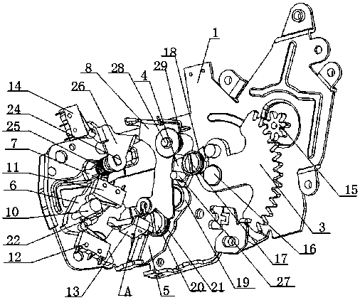
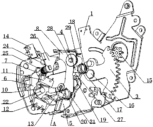
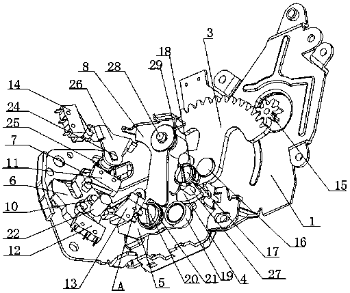
[0024] This embodiment provides an electric lock, such as Figures 1 to 4 As shown, it mainly consists of a base 1, a locking motor, a gear plate 3, a driving block 4, a toggle lever 5, a tiger mouth lock block 6, a limit block 7, an unlocking piece 8, an unlocking motor (not shown in the figure), The controller, the first contact switch 11, the second contact switch 12, the third contact switch 13 and the fourth contact switch 14 are composed. The locking motor is fixed on the base 1, and its output shaft 15 meshes with one side of the gear plate 3. , the other side of the gear plate 3 is rotatably connected to the base through the rotating shaft F 16; the drive block 4 is rotatably connected to the other side of the gear plate 3 through the rotating shaft A 17 and the first rotary member 18, and the first rotary member 18 is preferably Use torsion spring, its one end is fixedly connected with driving block 4, and the other end is fixedly connected with gear plate 3, and the ...


PUM


Abstract

The invention relates to the field of electric locks, and discloses an electric lock. The electric lock comprises a base, a locking motor, a gear piece, a driving block, a shifting rod, a jaw lockingblock, a limiting block, an unlocking piece and an unlocking motor, wherein the locking motor is fixed to the base, an output shaft of the locking motor is meshed with one side of the gear piece, theother side of the gear piece is rotationally connected with the base, and the driving block is rotatably connected with the other side of the gear piece; the shifting rod, the jaw locking block, the limiting block and the unlocking piece are all rotatably connected with the base, and the driving block, the shifting rod, the jaw locking block and the limiting block are rotationally connected in sequence; and an output shaft of the unlocking motor is connected with one end of the unlocking piece through a pull wire, and the unlocking piece, the limiting block and the driving block are rotationally connected. Compared with the prior art, the electric lock can be electrically locked and can be manually locked, the structural design is reasonable, safety and reliability are achieved, the energyconsumption is low, and the cost is reduced.

Description

technical field [0001] The invention relates to the field of electric locks, in particular to an electric lock. Background technique [0002] At present, bus doors and passenger car doors are not locked with locks, and the bus is completely pulled by the cylinder to hold the door. If the cylinder is cut off or leaks, the door can be opened automatically, which is very unsafe. Present passenger cars mainly rely on the lifting and self-locking of the doors. If the lifting mechanism is damaged, the doors will also open automatically, which is also very unsafe. And these two kinds of car doors all can't manually close the car door when the car door driving mechanism is damaged, in order to improve the safety and convenience of the car door, researchers in the field mainly put the object of study on the structure of the car door lock. Contents of the invention [0003] Purpose of the invention: Aiming at the problems existing in the prior art, the present invention provides an...

Claims


Application Information

Patent Timeline
IPC IPC(8): E05B83/36E05B81/06E05B79/10E05B81/32E05B85/00
CPCE05B79/10E05B81/06E05B81/32E05B83/36E05B85/00
Inventor 吕思华
Owner 金湖县微晶控制系统有限公司
Why Eureka
Try Eureka