
A distribution plate that can distribute different flow differences

A valve plate and flow difference technology, which is applied to the components of the pumping device for elastic fluids, pump elements, liquid fuel engines, etc., to achieve the effect of great practical value

Active Publication Date: 2021-08-03
TAIYUAN UNIV OF TECH
View PDF6 Cites 0 Cited by
  • Summary
  • Abstract
  • Description
  • Claims
  • Application Information

AI Technical Summary

Problems solved by technology

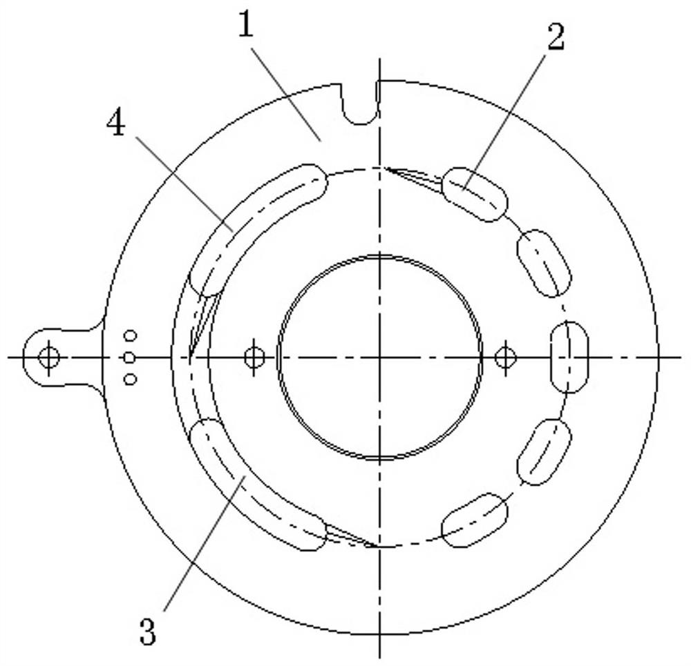
The distribution plate of the present invention is used in an axial plunger pump with an asymmetric flow distribution structure, so that one pump can solve the asymmetric flow rate between the two cavities of the differential oil cylinder with different cavity differences, and control the action of the differential oil cylinder with different cavity differences.

Method used


Image

  • A distribution plate that can distribute different flow differences
  • A distribution plate that can distribute different flow differences
  • A distribution plate that can distribute different flow differences

Examples


Embodiment Construction

[0027] The technical solution of the present invention will be further described below in conjunction with the accompanying drawings. It should be pointed out that the descriptions of specific embodiments in this section should not be considered as having any limiting effect on the protection scope of the present invention. In addition, the embodiments in this section and the features in the embodiments may provide further evidence for the claims, where there is no conflict.

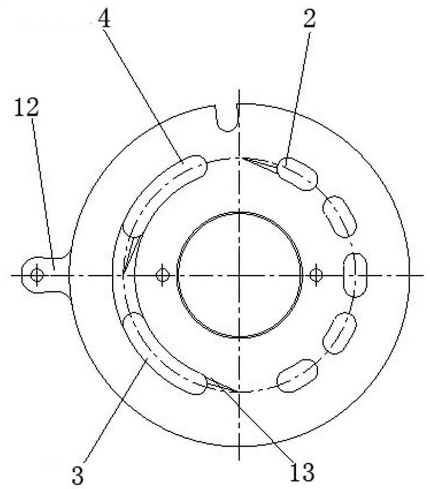
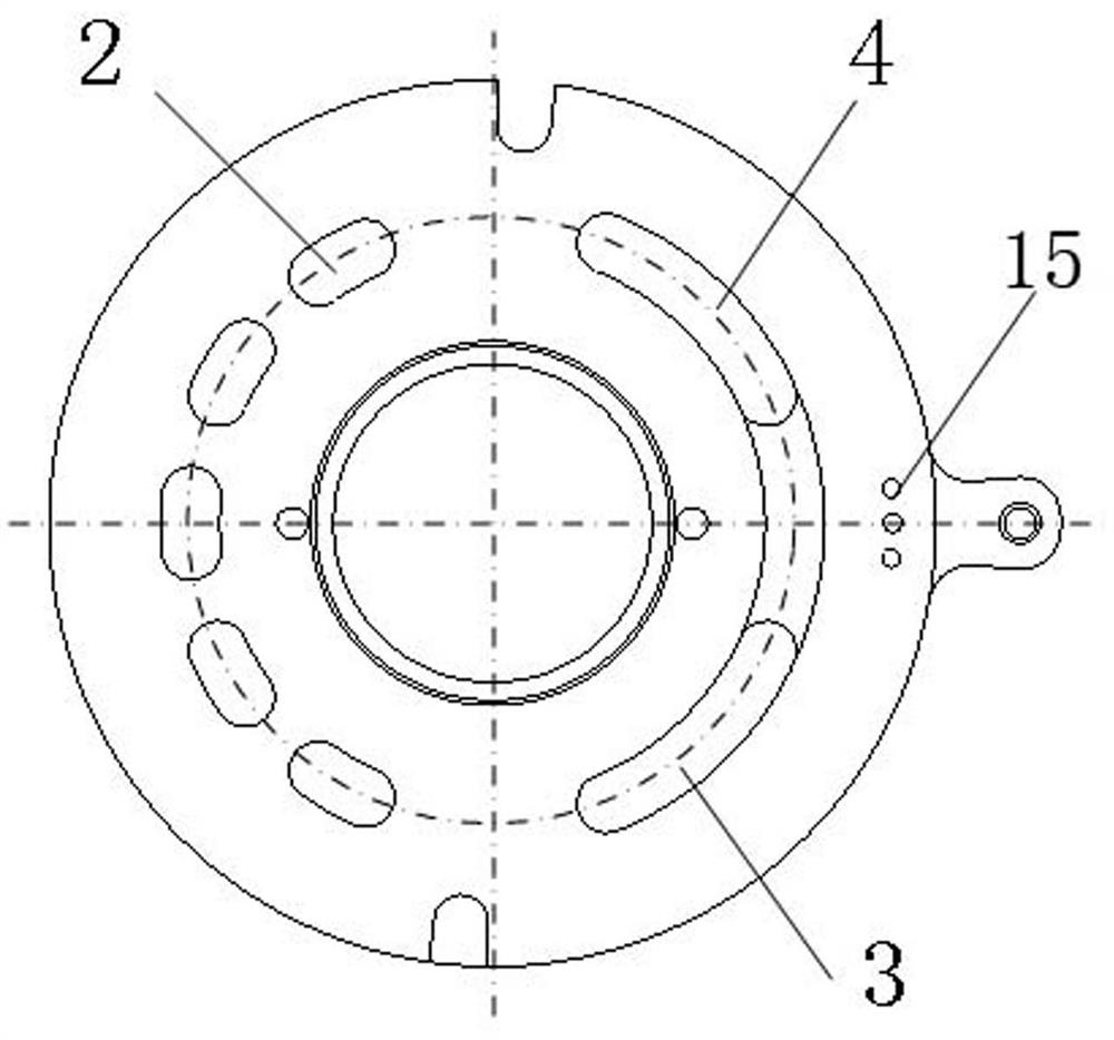
[0028] A flow distribution plate capable of distributing different flow differences according to the present invention specifically includes: a plurality of oil suction windows C2 and two oil discharge windows on the flow distribution plate, wherein the two oil discharge windows include: A oil discharge window 3, B oil discharge window window 4. The oil suction window C, the oil discharge window A, and the oil discharge window B are all arc-shaped waist holes, and the three flow distribution windows are...


PUM


Abstract

The invention discloses a flow distribution plate capable of distributing different flow differences for a high-pressure axial plunger pump with multiple oil outlets. The distribution plate is composed of three layers: the upper layer, the middle layer and the bottom layer. The raised part of the distribution window of the middle layer is in high pressure sealing fit with the positioning part of the upper layer and the bottom layer. The distribution plate is a series structure of multiple distribution windows: there are multiple oil suction windows and two (or more) oil discharge windows, one side is the distribution window C, and the other side is two (or more) distribution windows arranged in series A, B, multiple flow distribution windows are located on the same graduation circle. The middle layer of the distribution plate can rotate freely through the servo control drive, changing the area size of the A and B distribution windows, and through the adjustment of the middle layer of the distribution plate, the flow rate of the A and B distribution windows can be changed, so that the two distribution windows output different flow rates , corresponding to the two chambers of the differential oil cylinder with different flow differences, the action of the differential oil cylinder with different flow differences can be directly controlled with one pump, and the practical value is high.

Description

technical field [0001] The invention belongs to the field of hydraulic technology, and in particular relates to a flow distribution plate capable of distributing different flow differences. Background technique [0002] At present, the direct pump control technology has made great progress. The high dynamic response servo and proportional axial piston variable pumps have been successfully developed, and the variable speed control technology has been introduced. These technologies have achieved good results in pump control symmetrical cylinders. However, the effect is not ideal when applied to differential cylinders; the reason is that these pumps can only output symmetrical flow, and if they are directly connected to differential cylinders, many auxiliary methods are required. When a single axial piston variable pump is used to directly control the movement of the differential cylinder, due to the volume difference between the two chambers of the differential cylinder, the f...

Claims


Application Information

Patent Timeline
IPC IPC(8): F04B53/00
CPCF04B53/00
Inventor 张晓刚权龙
Owner TAIYUAN UNIV OF TECH
Learn More