An experimental instrument for dynamic imaging of radiation and contraction of variable angle mirrors

A technology of dynamic imaging and angle, applied in the direction of instruments, teaching models, educational tools, etc., can solve problems such as comparison, lack of novelty and creativity, and insufficient physical content

Active Publication Date: 2021-06-04
QIQIHAR UNIVERSITY
View PDF0 Cites 0 Cited by
  • Summary
  • Abstract
  • Description
  • Claims
  • Application Information

AI Technical Summary

Problems solved by technology

[0002] In geometrical optics, imaging is one of the important contents in teaching. It is widely used, from physical experiments to science and technology education and toys, such as two plane mirrors (one is a semi-transparent membrane mirror) parallel demonstration peep infinite, triangular prism Distributed demonstration kaleidoscopes, etc., in order to increase the interest of students in understanding the imaging of plane mirrors, the kaleidoscopes designed by people are very popular. The kaleidoscope images in the prior art are static, or the lens barrel is rotated, or the object that is artificially imaged is driven by a motor. Rotation, or shaking, etc., the angle between these mirrors is fixed, it is impossible to compare the images of different angles of the mirrors in one device, and the physical content of its dynamic performance is not deep enough, lacking novelty and Creativity, how to realize the plane mirror imaging with variable angle (variable included angle), and the dynamic object does not rely on electric, manual and other artificial drives, and can last for a long time. A comprehensive new experiment that is simple, low-cost, and convenient for students to explore and research. This patent will solve this problem

Method used


Image

  • An experimental instrument for dynamic imaging of radiation and contraction of variable angle mirrors
  • An experimental instrument for dynamic imaging of radiation and contraction of variable angle mirrors
  • An experimental instrument for dynamic imaging of radiation and contraction of variable angle mirrors

Examples


Embodiment Construction

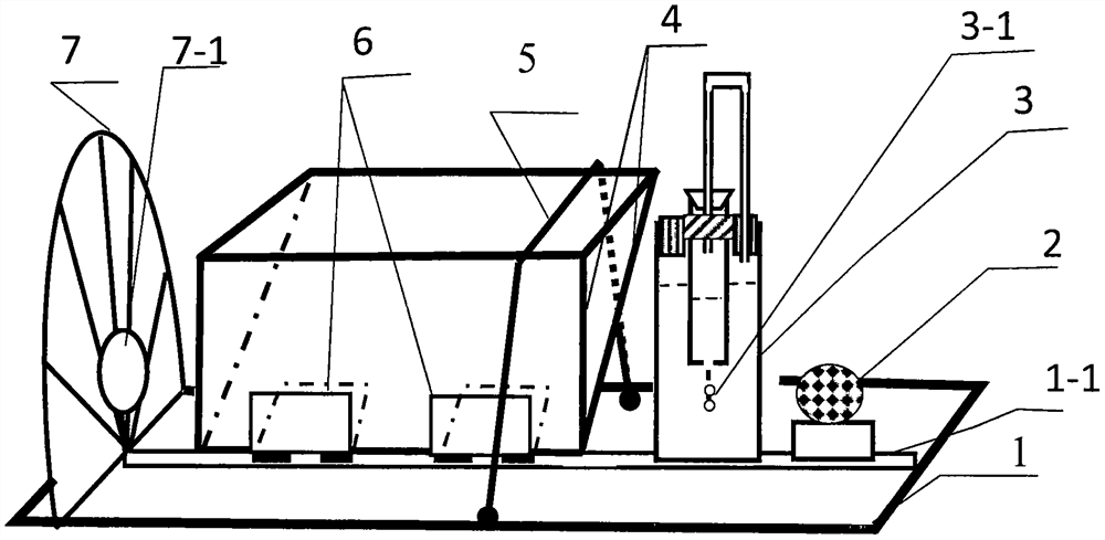
[0013] as attached image 3 : A dynamic imaging experiment apparatus for radiation and shrinkage of a variable angle mirror, mainly composed of a horizontal plate 1, a central groove 1-1, a lighting lamp 2, an automatic vortex ring former 3, a vortex ring 3-1, a plane mirror 4, and an elastic Belt 5, hinge 6, half-circle instrument 7, observation hole 7-1 constitute, it is characterized in that: two elongated flat mirrors 4 of equal size are respectively fixed on the two pages of movable hinge 6 (the reflective surface is opposite, The angle between the two strip-shaped plane mirrors can vary from 0 to 180 degrees), the central axis of the horizontal plate 1 has a central groove 1-1, and the hinge 6 axis on the plane mirror 4 is in the central groove 1-1 In 1 [limit the position of the top corners (top edges) of the two plane mirrors 4]; an elastic band 5 is wound around the edges of the two strip-shaped plane mirrors 4, and the two ends of the elastic band 5 are stretched (ti...


PUM


Abstract

An experimental instrument for radiation and contraction dynamic imaging of variable angle mirrors, mainly composed of a horizontal plate, a central groove, a lighting lamp, an automatic vortex ring former, a vortex ring, a flat mirror, an elastic belt, a hinge, a semicircle, and an observation hole , which is characterized in that: two strip-shaped flat mirrors of equal size are respectively fixed on the two pages of the movable hinge, the elastic band can control the angle between the two flat mirrors and the overall position of the two flat mirrors in space, and the semicircle The extension line of the vertical intersection line is fixed on the horizontal plate; the automatic vortex ring former is fixed on the horizontal plate, and the movement direction of the vortex ring in the automatic vortex ring former is extended on the bisecting plane of the angle between the two long flat mirrors On the surface, the lighting lamp is fixed on the horizontal plate. Realize the jellyfish-like vortex ring motion that is alternately changed by non-electric power to study the technology of imaging radiation and contraction motion.

Description

technical field [0001] This patent relates to the demonstration of a plane mirror imaging dynamic experimental instrument with variable angle, which belongs to the field of physical experimental instruments. Background technique [0002] In geometrical optics, imaging is one of the important contents in teaching. It is widely used, from physical experiments to science and technology education and toys, such as two plane mirrors (one is a semi-transparent membrane mirror) parallel demonstration peep infinite, triangular prism Distributed demonstration kaleidoscopes, etc., in order to increase the interest of students in understanding the imaging of plane mirrors, the kaleidoscopes designed by people are very popular. The kaleidoscope images in the prior art are static, or the lens barrel is rotated, or the object that is artificially imaged is driven by a motor. Rotation, or shaking, etc., the angle between these mirrors is fixed, it is impossible to compare the images of dif...

Claims


Application Information

Patent Timeline
Patent Type & Authority Patents(China)
IPC IPC(8): G09B23/22
CPCG09B23/22
Inventor 梁法库梁帅闫公敬
Owner QIQIHAR UNIVERSITY
Why Eureka
Try Eureka